


Best Practices for EVPN MC-LAG (unnumbered BGP)
This document introduces the recommended baseline solution, configuration guide, and maintenance guide in detail for data center series switches in EVPN MC-LAG scenarios, to achieve VxLAN Anycast Gateway functionality under leaf-spine infrastructure.
Intended Audience
Section titled “Intended Audience”This manual is intended for project planning, design and implementation personnel. They are expected to:
- Be familiar with Asterfusion data center series switches.
- Be familiar with EVPN MC-LAG fundamentals.
EVPN MC-LAG Overview
Section titled “EVPN MC-LAG Overview”EVPN MC-LAG is a dual-homed and dual-active VxLAN distributed gateway solution widely adopted in data center environments. By combining the advantages of EVPN and MC-LAG technologies, this solution provides support for high reliability in access scenarios, achieving load balancing, fault tolerance, independent nodes upgrades and other functions.
Basic Concepts
Section titled “Basic Concepts”MC-LAG peer
Section titled “MC-LAG peer”The two Leaf nodes connected to the same device are called MC-LAG peer. The nodes perform an active and a standby role. The node with the smaller local IP address is designated as active endpoint, and the one with larger local IP address serves as standby endpoint. The distinction between active and standby applies only to the control plane. In the forwarding plane, MC-LAG peers operate with equal status, independently determining traffic forwarding paths based on their local forwarding decisions.
ICCP (Inter-Chassis Communication Protocol), defined in RFC 7275, is utilized in this scheme for establishing ICCP connections between MC-LAG peer to synchronize interface statuses, table entries, and perform role negotiation.
Keep-alive link
Section titled “Keep-alive link”The keep-alive link is a heartbeat detection link, typically implemented as a direct Layer 3 connection between MC-LAG peer, periodically sends heartbeat packet. It’s used for transmitting ICCP control protocol packets, synchronizing table information, establishing MC-LAG peer relationships, and implementing configuration consistency checks.
Peer-link
Section titled “Peer-link”The peer-link refers to a direct physical link between MC-LAG peers, used to forward traffic when there is a failure in downstream links. Generally, it is recommended to be shared with keep-alive link for operational efficiency and resource optimization.
DAD link
Section titled “DAD link”The DAD (Dual Active Detection) link is a layer 3 interoperable link used by MC-LAG peer to send dual-active detection packets, applicable in scenarios when the peer-link and keep-alive link are shared. When the keep-alive link is detected as disconnected, the system will automatically shut down all interfaces on the standby node except logical interfaces, management ports, and peer-link interfaces.
MC-LAG member lag
Section titled “MC-LAG member lag”The port-channel on MC-LAG peer connecting to the same servers or hosts are called member lags.
MC-LAG working mode
Section titled “MC-LAG working mode”MC-LAG operates in two modes: dual-active mode and active-standby mode. In dual-active mode, both the active and standby node will forward traffic, achieving load sharing across member lags. In active-standby mode, usually only the active node will forward traffic flows, while the standby one will not. The standby node will remain inactive (block traffic) until a failover occurs. Currently, the MC-LAG solution is in the dual-active mode and does not support the active-standby mode.
A VTEP (VxLAN Tunnel Endpoint) is an edge node in a VxLAN network, responsible for encapsulating and decapsulating VxLAN packets and communicating with the underlying physical network. In a distributed gateway architecture, the VTEP also serves as a gateway, providing layer 3 routing functionality for traffic within the VxLAN overlay.
VxLAN Anycast Gateway
Section titled “VxLAN Anycast Gateway”The VxLAN anycast gateway is an architecture used to achieve more efficient and flexible routing and bridging functions in a VxLAN network. By distributing gateway functionality across multiple VTEP nodes, this approach allows each VTEP to perform layer 2/layer 3 forwarding independently, thereby enhancing overall performance and resiliency.
Networking Solution
Section titled “Networking Solution”A typical EVPN MC-LAG networking is shown in the figure below.
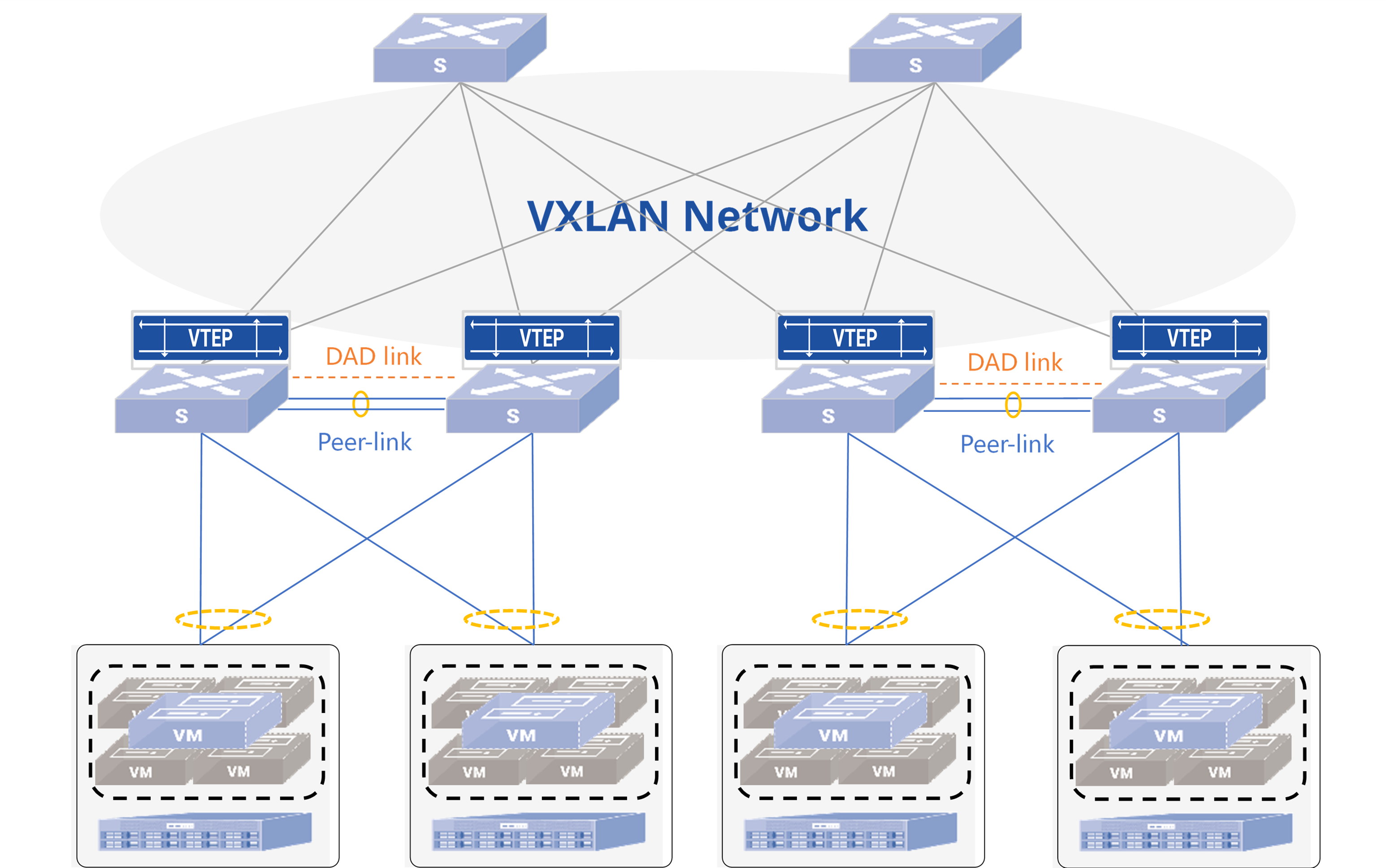
Description: Service servers are dual-connected to Server Leaf nodes, which set up EVPN MC-LAG as layer 3 anycast gateways. Spine nodes are connected to Leaf nodes, running routing protocols for underlay reachability. The following table shows the recommended deployment approach for this solution.
Table 1 Recommended deployment
| Item | Recommended approaches to deploy |
|---|---|
| Interconnection of Leaf and Spine | - BGP is the most commonly used routing protocol when deploying data center topologies. We recommend using BGP protocol for underlay route reachability. To achieve the separation of underlay and overlay routes, we recommend using the interconnect port IP to establish underlay BGP neighbors and Loopback0 IP to establish overlay BGP neighbors. - It is recommended to use high-speed interfaces for interconnection between Leaf and Spine. You could configure physical layer 3 ports or into a link aggregation group to increase the bandwidth of uplink. - It is recommended that Spine nodes are configured with the same ASN to minimize unnecessary route exchanges, thus reducing resource usage. - It is required that a pair of MC-LAG peer are configured with the same ASN. |
| Deploy peer-link and keep-alive link | - It is recommended to use high-speed interfaces for interconnection and configure static aggregation links as peer-link on MC-LAG peer. - It is recommended to share peer-link with keep-alive link. - The peer-link shall be configured in tagged mode and added to both the dedicated VLAN for keep-alive link and the service VLAN for hosts. The IP address of the dedicated VLAN interface (VLANIF) is used as the communication endpoint for the ICCP connection. |
| Deploy DAD link | - It is recommended to use an independent low-speed interface for interconnection as DAD link. The solution does not support using the management port to deploy DAD link. - It is recommended to configure the keep-alive link first and ensure the MC-LAG keep-alive status is active before configuring DAD link, preventing incorrect error-down of node ports due to premature activation of dual-active detection mechanisms. - The DAD link shall not share physical or logical link with peer-link or keep-alive link. |
| Deploy MC-LAG member lags | - It is recommended to use low-speed interfaces for MC-LAG member lags. Multiple members can be configured. - For reliability reasons, it is recommended to use LACP dynamic aggregation. You could enable fast-rate (short timeout) on both sides to improve the performance of fault convergence. |
| Servers/switches connected to Leaf nodes | - It is recommended to use bond4 (load sharing) for access on the server side when configuring the bond. - If the servers are installed by PXE, the feature LACP fallback is required to be enabled on the port-channel of one of the connected Leaf. |
| Layer 3 VxLAN anycast gateway | - When deploying layer 3 VxLAN gateways on Leaf, all nodes should be configured with the same IP and MAC addresses on the VLANs shared between them. - For a pair of MC-LAG peers, the MAC addresses configured on VRFs (Virtual Routing and Forwarding instances) bound to the same Layer 3 VNI (L3VNI) shall be identical. - It is recommended to configure Loopback1 IP as the local EVPN VTEP IP. For a pair of MC-LAG peers, the VTEP IP shall be identical. - At the same time, this solution provides support for layer 3 connectivity when required. The establishment of routing protocols between Leaf peers and access nodes is achieved by enabling Unique-IP feature on Leaf nodes and configuring different Primary IP and MAC addresses for VLANs when required. |
| Load Balance | - In a data center network, usually the BGP ASN of each node is different, and the AS-path of the routes from other nodes are different as well. Therefore, it is necessary to enable the multi-path functionality on nodes that receive routes to achieve load balancing of services. |
| Fault Tolerance | - It is recommended to configure monitor link groups on the Leaf switches to guarantee fast failover in case of uplink or node failures. - It is recommended to configure startup-delay on the uplink interfaces of MC-LAG nodes. This ensures that uplink interfaces remain in a down state until MC-LAG information synchronization is complete, thereby minimizing packet loss during traffic switchback scenarios caused by node reboots or failure recovery. - It is recommended to configure the BGP graceful restart (GR) and BGP max-med on-startup functionalities on Leaf and Spine switches according to the actual needs for ensuring fast failover of routing protocols in case of node-level failures. |
hint{type=“info”} NOTES:
- For establishing a BGP neighbor with loopback, it is required to configure EBGP hops greater than 1 and designate the source interface.
Configure Leaf Nodes
Section titled “Configure Leaf Nodes”Configure interconnect interfaces and loopback
Section titled “Configure interconnect interfaces and loopback”Table 7 Configure interconnect interfaces and loopback on Leaf nodes
| Descriptions | Leaf1 | Leaf2 |
|---|---|---|
| Configure the IP address of the interface interconnected with Spine. | interface ethernet 0/48 description to_Spine1 ipv6 use-link-local ! interface ethernet 0/52 description to_Spine2 ipv6 use-link-local ! | interface ethernet 0/48 description to_Spine1 ipv6 use-link-local ! interface ethernet 0/52 description to_Spine2 ipv6 use-link-local ! |
| Configure the IP address of Loopback0 as the router-ID as well as the source interface for establishing BGP neighbors. | interface loopback 0 ip address 172.16.1.179/32 ! | interface loopback 0 ip address 172.16.1.166/32 ! |
| Configure the IP address of Loopback1 as local VTEP IP. | interface loopback 1 ip address 172.16.2.179/32 ! | interface loopback 1 ip address 172.16.2.179/32 ! |
Configure underlay BGP neighbors
Section titled “Configure underlay BGP neighbors”Create two BGP peer groups on all Leaf nodes.
- PEER_to_Spine: used to establish underlay BGP neighbors with Spine nodes.
- PEER_to_Spine_EVPN: used to establish overlay BGP neighbors with Spine nodes.
Table 8 Configure underlay BGP neighbors on Leaf nodes
| Descriptions | Leaf1 | Leaf2 |
|---|---|---|
| Create a route-map and an IP prefix list to advertise Loopback. | route-map advertise_loopback permit 10 match ip address prefix-list loopback exit ! ip prefix-list loopback seq 10 permit 172.16.1.0/24 ge 24 ip prefix-list loopback seq 20 permit 172.16.2.0/24 ge 24 ! | route-map advertise_loopback permit 10 match ip address prefix-list loopback exit ! ip prefix-list loopback seq 10 permit 172.16.1.0/24 ge 24 ip prefix-list loopback seq 20 permit 172.16.2.0/24 ge 24 ! |
| Configure BGP ASN and router-ID. Enable BGP GR, max-med on start-up and multi path features. | router bgp 65100 bgp router-id 172.16.1.179 no bgp ebgp-requires-policy bgp bestpath as-path multipath-relax bgp max-med on-startup 120 bgp graceful-restart | router bgp 65100 bgp router-id 172.16.1.166 no bgp ebgp-requires-policy bgp bestpath as-path multipath-relax bgp max-med on-startup 120 bgp graceful-restart |
Create a peer-group named PEER_to_Spine and enable BFD. | neighbor PEER_to_Spine peer-group neighbor PEER_to_Spine remote-as external neighbor PEER_to_Spine bfd neighbor ethernet 0/48 interface peer-group PEER_to_Spine neighbor ethernet 0/52 interface peer-group PEER_to_Spine ! | neighbor PEER_to_Spine peer-group neighbor PEER_to_Spine remote-as external neighbor PEER_to_Spine bfd neighbor ethernet 0/48 interface peer-group PEER_to_Spine neighbor ethernet 0/52 interface peer-group PEER_to_Spine ! |
| Advertise Loopback IPs. | address-family ipv4 unicast redistribute connected route-map advertise_loopback neighbor PEER_to_Spine route-map advertise_loopback out exit-address-family exit ! | address-family ipv4 unicast redistribute connected route-map advertise_loopback neighbor PEER_to_Spine route-map advertise_loopback out exit-address-family exit ! |
After finishing the configurations above, you can check of underlay BGP status through command show ip bgp summary:
mclag-leaf-1# show ip bgp summary
IPv4 Unicast Summary (VRF default):BGP router identifier 172.16.1.179, local AS number 65100 vrf-id 0BGP table version 9RIB entries 13, using 2392 bytes of memoryPeers 2, using 1447 KiB of memoryPeer groups 2, using 128 bytes of memory
Neighbor        V         AS   MsgRcvd   MsgSent   TblVer  InQ OutQ  Up/Down State/PfxRcd   PfxSnt Descethernet 0/48       4      65165       133       133        0    0    0 01:58:22       4        7   N/Aethernet 0/52       4      65165       131       133        0    0    0 01:58:11       4        7   N/A
Total number of neighbors 2
There are two messages you could take notice of in the output.
- The field “State/PfxRcd” shows the state of the BGP session. If the state is Idle/Connect/Active, it means that the BGP session establishment is abnormal. If it is displayed as a number, it means that the BGP session has established successfully, and the number is the count of route prefixes received from BGP peer.
- The field “Up/Down” shows the time duration for which the BGP session has been in the current state.
Configure overlay BGP neighbors
Section titled “Configure overlay BGP neighbors”Table 9 Configure overlay BGP neighbors on Leaf nodes
| Descriptions | Leaf1 | Leaf2 |
|---|---|---|
Create a peer-group named PEER_to_Spine_EVPN. Enable BGP EVPN address-family and specify the source interface as Loopback 0. | router bgp 65100 neighbor PEER_to_Spine_EVPN peer-group neighbor PEER_to_Spine_EVPN remote-as external neighbor PEER_to_Spine_EVPN ebgp-multihop 5 neighbor PEER_to_Spine_EVPN update-source 172.16.1.179 neighbor 172.16.1.165 peer-group PEER_to_Spine_EVPN neighbor 172.16.1.167 peer-group PEER_to_Spine_EVPN ! address-family ipv4 unicast no neighbor PEER_to_Spine_EVPN activate exit-address-family ! address-family l2vpn evpn neighbor PEER_to_Spine_EVPN activate advertise-all-vni exit-address-family exit ! | router bgp 65100 neighbor PEER_to_Spine_EVPN peer-group neighbor PEER_to_Spine_EVPN remote-as external neighbor PEER_to_Spine_EVPN ebgp-multihop 5 neighbor PEER_to_Spine_EVPN update-source 172.16.1.166 neighbor 172.16.1.165 peer-group PEER_to_Spine_EVPN neighbor 172.16.1.167 peer-group PEER_to_Spine_EVPN ! address-family ipv4 unicast no neighbor PEER_to_Spine_EVPN activate exit-address-family ! address-family l2vpn evpn neighbor PEER_to_Spine_EVPN activate advertise-all-vni exit-address-family exit ! |
After finishing the configurations above, you can check overlay BGP status through command show bgp l2vpn evpn summary.
mclag-leaf-1# show bgp l2vpn evpn summaryBGP router identifier 172.16.1.179, local AS number 65100 vrf-id 0BGP table version 0RIB entries 151, using 27 KiB of memoryPeers 2, using 1447 KiB of memoryPeer groups 1, using 64 bytes of memoryNeighbor V AS MsgRcvd MsgSent TblVer InQ OutQ Up/Down State/PfxRcd PfxSnt Desc172.16.1.165 4 65165 196 328 0 0 0 00:05:52 2153 2181 N/A172.16.1.167 4 65165 136 332 0 0 0 00:05:53 2087 2181 N/ATotal number of neighbors 2Configure MC-LAG
Section titled “Configure MC-LAG”Table 10 Configure MC-LAG on Leaf nodes
| Descriptions | Leaf1 | Leaf2 |
|---|---|---|
| Configure the VLANIF for establishing MC-LAG. | vlan 4094 ! interface vlan 4094 ip address 40.94.0.1/30 exit ! | vlan 4094 ! interface vlan 4094 ip address 40.94.0.2/30 exit ! |
| Configure the peer-link and add to the VLAN. | interface link-aggregation 9999 switchport trunk vlan 4094 exit ! interface ethernet 0/72 link-aggregation-group 9999 storm-suppress broadcast packets 1000 storm-suppress multicast packets 1000 storm-suppress unknown-unicast packets 1000 exit ! interface ethernet 0/76 link-aggregation-group 9999 storm-suppress broadcast packets 1000 storm-suppress multicast packets 1000 storm-suppress unknown-unicast packets 1000 exit ! | interface link-aggregation 9999 switchport trunk vlan 4094 exit ! interface ethernet 0/72 link-aggregation-group 9999 storm-suppress broadcast packets 1000 storm-suppress multicast packets 1000 storm-suppress unknown-unicast packets 1000 exit ! interface ethernet 0/76 link-aggregation-group 9999 storm-suppress broadcast packets 1000 storm-suppress multicast packets 1000 storm-suppress unknown-unicast packets 1000 exit ! |
| Configure a MC-LAG domain. | mclag domain 1 local-address 40.94.0.1 peer-address 40.94.0.2 peer-link link-aggregation 9999 commit ! | mclag domain 1 local-address 40.94.0.2 peer-address 40.94.0.1 peer-link link-aggregation 9999 commit ! |
| Configure the DAD link. | interface ethernet 0/47 ip address 40.95.0.1/30 exit ! mclag domain 1 dad local-address 40.95.0.1 dad peer-address 40.95.0.2 commit ! | interface ethernet 0/47 ip address 40.95.0.2/30 exit ! mclag domain 1 dad local-address 40.95.0.2 dad peer-address 40.95.0.1 commit ! |
:hint{type="info"} NOTES:
- The command
arp broadcast disableis supported only in version R0408P00 and later. If the switch returns an error indicating that the command is not supported, use the following commands:
policy-map type copp copp-system-policy class copp-system-arp  trap-action trap
2. Silent terminals are those who do not actively send ARP requests.
### Configure downstream cross-device aggregation groups
Table 12 Configure downstream cross-device aggregation groups on Leaf nodes
| Descriptions                                                                             | Leaf1                                                                                                                                                                                                                                                                                                                                                                                     | Leaf2                                                                                                                                                                                                                                                                                                                                                                                     || --------------------------------------------------------------------------------------------------------------------- | ---------------------------------------------------------------------------------------------------------------------------------------------------------------------------------------------------------------------------------------------------------------------------------------------------------------------------------------------------------------------------------------------------------------------- | ---------------------------------------------------------------------------------------------------------------------------------------------------------------------------------------------------------------------------------------------------------------------------------------------------------------------------------------------------------------------------------------------------------------------- || Create a dynamic aggregation group and enable fast-rate.                                                              | interface link-aggregation 100<br /> lacp fast-ratecommit<br />!<br />interface link-aggregation 101<br /> lacp fast-rate<br /> commit<br />!                                                                                                                                                                                                                                                                          | interface link-aggregation 100<br /> lacp fast-rate<br /> commit<br />!<br />interface link-aggregation 101<br /> lacp fast-rate<br /> commit<br />!                                                                                                                                                                                                                                                                   || Join the member lag of the MC-LAG.                                                                                    | mclag domain 1<br /> member lag 100<br /> member lag 101<br />!                                                                                                                                                                                                                                                                                                                                                        | mclag domain 1<br /> member lag 100<br /> member lag 101<br />!                                                                                                                                                                                                                                                                                                                                                        || (Optional) If the servers are installed via PXE, the fallback feature is required to be enabled on one of Leaf nodes. | interface link-aggregation 100<br /> lacp fallback<br /> commit<br />!<br />interface link-aggregation 101<br /> lacp fallback<br /> commit<br />!                                                                                                                                                                                                                                                                     | -                                                                                                                                                                                                                                                                                                                                                                                                                      || Add to the service VLAN.                                                                                              | interface link-aggregation 100<br /> switchport trunk vlan 10<br />!<br />interface link-aggregation 101<br /> switchport trunk vlan 20<br />!                                                                                                                                                                                                                                                                         | interface link-aggregation 100<br /> switchport trunk vlan 10<br />!<br />interface link-aggregation 101<br /> switchport trunk vlan 20<br />!                                                                                                                                                                                                                                                                         || Configure the member of the LAG and enable storm suppression for BUM.                                                 | interface ethernet 0/0<br /> link-aggregation-group 100<br /> storm-suppress broadcast packets 1000<br /> storm-suppress multicast packets 1000<br /> storm-suppress unknown-unicast packets 1000<br />!<br />interface ethernet 0/1<br /> link-aggregation-group 101<br /> storm-suppress broadcast packets 1000<br /> storm-suppress multicast packets 1000<br /> storm-suppress unknown-unicast packets 1000<br />! | interface ethernet 0/0<br /> link-aggregation-group 100<br /> storm-suppress broadcast packets 1000<br /> storm-suppress multicast packets 1000<br /> storm-suppress unknown-unicast packets 1000<br />!<br />interface ethernet 0/1<br /> link-aggregation-group 101<br /> storm-suppress broadcast packets 1000<br /> storm-suppress multicast packets 1000<br /> storm-suppress unknown-unicast packets 1000<br />! |
After finishing the configurations above, you can check the port-channel status through command **show link-aggregation summary**.
```plaintextmclag-leaf-1# show link-aggregation summaryFlags: A - active, I - inactive, Up - up, Dw - Down, N/A - not available,       S - selected, D - deselected, * - not syncedNo.    Team Dev         Protocol         Ports            Description-----  ---------------  ---------------  ---------------  -------------0100   lag 100          LACP(A)(Up)      0/0      (S)     N/A0101   lag 101          LACP(A)(Up)      0/1      (S)     N/A9999   lag 9999         LACP(A)(Up)      0/72     (S)     N/A                                         0/76     (S)
In the example above, “Up” means the current state of the port-channel is normal, and “S” means the member port is selected.
Configure EVPN and VxLAN mapping
Section titled “Configure EVPN and VxLAN mapping”Table 13 Configure EVPN and VxLAN mapping on Leaf nodes
| Descriptions | Leaf1 | Leaf2 |
|---|---|---|
| Configure EVPN local VTEP IP. The VTEP IP of MC-LAG peer shall be the same. | interface vxlan 0 source 172.16.2.179 exit | interface vxlan 0 source 172.16.2.179 exit |
| Configure layer 2 VxLAN mapping. | vlan 10 vni 100 ! vlan 20 vni 200 ! | vlan 10 vni 100 ! vlan 20 vni 200 ! |
| Configure layer 3 VxLAN mapping. | vrf 10123 vni 10000 exit-vrf ! | vrf 10123 vni 10000 exit-vrf ! |
After configurations you can check VxLAN tunnels through command show vxlan tunnel.
mclag-leaf-1# show vxlan tunnel+--------------+-------+--------+-------+| RemoteVTEP | VNI | VLAN | VRF |+==============+=======+========+=======+| 172.16.2.170 | 100 | 10 | |+--------------+-------+--------+-------+| 172.16.2.170 | 200 | 20 | |+--------------+-------+--------+-------+| 172.16.2.170 | 300 | 30 | |+--------------+-------+--------+-------+| 172.16.2.170 | 10000 | | 10123 |+--------------+-------+--------+-------+Configure a monitor link group
Section titled “Configure a monitor link group”The purpose of configuring an interface linkage group is to safeguard the switchover in case of link/node failure and reduce packet loss. When the status of all uplink ports changes from up to down, the downlink ports will automatically go down; when the status of some uplink ports is restored, the downlink ports will be delayed for a period of time before resuming up.
The purpose of configuring interface delayed startup is to reduce packet loss in the traffic cutback scenario when the node reboots or fails to recover. When the node reboots and recovers, the physical interfaces will be delayed for a certain period of time before resuming up, and the default delayed startup time for all interfaces is 150 s. In large-scale terminal scenarios (when the number of terminals in the entire network exceeds 1K), the MC-LAG peer needs to synchronize a large number of table entries after startup, and if the upstream port has been restored to make the traffic cut back but the table entry synchronization is not yet completed, then packet loss will occur. Therefore, it is recommended to configure a delay time of 300 seconds or longer on the uplink port, and use the default delay time of 150 seconds on the rest of the interfaces, so that the peer-link and keep-alive links are restored before the uplink port, and sufficient time is reserved for the synchronization of MC-LAG table entries.
Table 14 Configure Monitor Link on Leaf nodes
| Descriptions | Leaf1 | Leaf2 |
|---|---|---|
| Create a monitor link group and specify the delay time. | monitor-link-group aster 60 ! | monitor-link-group aster 60 ! |
| Specify the physical port connected to the Spine as the uplink port and configure an interface delay of 300 seconds to start. | interface ethernet 0/48 monitor-link aster uplink startup-delay 300 ! interface ethernet 0/52 monitor-link aster uplink startup-delay 300 ! | interface ethernet 0/48 monitor-link aster uplink startup-delay 300 ! interface ethernet 0/52 monitor-link aster uplink startup-delay 300 ! |
| Specify the physical ports connected to servers as downlink. | interface ethernet 0/0 monitor-link aster downlink ! interface ethernet 0/1 monitor-link aster downlink ! | interface ethernet 0/0 monitor-link aster downlink ! interface ethernet 0/1 monitor-link aster downlink ! |
After configurations you can check monitor link through command show monitor-link.
mclag-leaf-1# show monitor-link+---------------+---------+----------------+------------------+-------------+------------+| Group Name | Delay | Uplink Ports | Downlink Ports | LACP LAGs | Networks |+===============+=========+================+==================+=============+============+| aster | 60 | 0/48 | 0/0 | | || | | 0/52 | 0/1 | | |+---------------+---------+----------------+------------------+-------------+------------+After completing the above configuration, you can check the startup delay time of the interface through command show interface startup_delay.
mclag-leaf-1# show interface startup_delayPort start up delay time---------- ---------------------0/47 1500/48 3000/52 3000/56 1500/60 1500/64 1500/68 1500/72 1500/76 150……(Optional) Configure for layer 3 service connectivity with user-side
Section titled “(Optional) Configure for layer 3 service connectivity with user-side”Usually, the user-side devices are attached to MC-LAG nodes with static routing. To cope with flexible and rapid deployment scenarios and meet the needs of rapid service growth, this solution provides the ability to establish dynamic routing protocols between MC-LAG nodes and user-side devices.
Specifically, it is necessary to enable the Unique-IP function of the corresponding VLAN on a pair of MC-LAG peers. The current Unique-IP on the MC-LAG supports both diff_mac and same_mac modes.
- In diff_mac mode, the shared VLAN on MC-LAG peer shall be configured with different IP and MAC.
- In same_mac mode, two Leaf peers need to be configured with different IPs and the same MAC address under the VLANIFs.
When establishing a routing protocol between MC-LAG peers via the peer-link link, the diff_mac mode is required. When establishing a routing protocol between an MC-LAG device and an access-side device, both modes are acceptable, but the same_mac mode is recommended. Below is a configuration example for establishing a BGP neighbor relationship between an MC-LAG device and the access-side device.
Table 15 (Optional) Configure for layer 3 service connectivity with user-side
| Descriptions | Leaf1 | Leaf2 |
|---|---|---|
| Create a VLAN and enable Unique-IP. configure different master IPs for establishing routing protocols and same slave IPs as VLAN gateways. | vlan 30 ! interface vlan 30 arp proxy mode evpn mac-address 00:00:00:30:00:00 vrf 10123 ip address 10.30.0.179/24 ip address 10.30.0.1/24 secondary ! mclag domain 1 unique-ip vlan 30 same_mac ! interface link-aggregation 9999 switchport trunk vlan 30 ! | vlan 30 ! interface vlan 30 arp proxy mode evpn mac-address 00:00:00:30:00:00 vrf 10123 ip address 10.30.0.166/24 ip address 10.30.0.1/24 secondary ! mclag domain 1 unique-ip vlan 30 same_mac ! interface link-aggregation 9999 switchport trunk vlan 30 ! |
| Add the LAG to the service VLAN | interface link-aggregation 101 switchport trunk vlan 30 ! | interface link-aggregation 101 switchport trunk vlan 30 ! |
| Create a BFD profile. The recommended BFD detection and reception interval is 1000ms, and the local detection multiplier is 3 by default. | bfd profile bfd_to_tor transmit-interval 1000 receive-interval 1000 exit ! exit ! | bfd profile bfd_to_tor transmit-interval 1000 receive-interval 1000 exit ! exit ! |
| To simplify the configuration, create a peer group for interacting with the user-side device, and enable BFD. | router bgp 65100 vrf 10123 no bgp ebgp-requires-policy neighbor PEER_to_Tor peer-group neighbor PEER_to_Tor remote-as external neighbor PEER_to_Tor ebgp-multihop 255 neighbor PEER_to_Tor bfd profile bfd_to_tor neighbor 10.30.0.3 peer-group PEER_to_Tor bgp listen range 10.30.0.0/24 peer-group PEER_to_Tor ! | router bgp 65100 vrf 10123 no bgp ebgp-requires-policy neighbor PEER_to_Tor peer-group neighbor PEER_to_Tor remote-as external neighbor PEER_to_Tor ebgp-multihop 255 neighbor PEER_to_Tor bfd profile bfd_to_tor neighbor 10.30.0.3 peer-group PEER_to_Tor bgp listen range 10.30.0.0/24 peer-group PEER_to_Tor ! |
| Advertise IPv4 address family routes to BGP EVPN neighbors. | address-family l2vpn evpn advertise ipv4 unicast exit-address-family exit ! | address-family l2vpn evpn advertise ipv4 unicast exit-address-family exit ! |
After configurations you can check BGP status through command show ip bgp [vrf vrf_name] summary.
Leaf1:
mclag-leaf-1# show ip bgp vrf 10123 summaryIPv4 Unicast Summary (VRF vrf 10123):BGP router identifier 10.200.0.1, local AS number 65100 vrf-id 211BGP table version 671RIB entries 51, using 9384 bytes of memoryPeers 1, using 723 KiB of memoryPeer groups 1, using 64 bytes of memoryNeighbor V AS MsgRcvd MsgSent TblVer InQ OutQ Up/Down State/PfxRcd PfxSnt Desc10.30.0.3 4 65236 1872 1770 0 0 0 00:10:59 25 27 N/ATotal number of neighbors 1Leaf2:
mclag-leaf-2# show ip bgp vrf 10123 summaryIPv4 Unicast Summary (VRF vrf 10123):BGP router identifier 10.200.0.1, local AS number 65100 vrf-id 94BGP table version 10342916RIB entries 51, using 9384 bytes of memoryPeers 1, using 723 KiB of memoryPeer groups 1, using 64 bytes of memoryNeighbor V AS MsgRcvd MsgSent TblVer InQ OutQ Up/Down State/PfxRcd PfxSnt Desc10.30.0.3 4 65236 27110 44103 0 0 0 00:13:16 27 27 N/ATotal number of neighbors 1(Optional) Optimize ARP parameters
Section titled “(Optional) Optimize ARP parameters”By default, the times of ARP aging probes of this series of switches is 5, and the ARP aging time is 300 seconds. In large-scale scenario (when the number of hosts in whole network is up to 1K), if the switch receives a large number of ARPs from hosts in a short time, it may not be able to process in time due to the limitation of CPU capability, resulting in the aging of some ARP entries, and then packet loss. At this time, you could increase ARP probe times to 10, and increase the aging time to 600/1200 seconds to ease the pressure on CPU and avoid packet loss.
Table 16 (Optional) Optimize ARP parameters on Leaf nodes
| Descriptions | Leaf1 | Leaf2 |
|---|---|---|
| Set ARP probe times. | arp probe times 10 ! | arp probe times 10 ! |
| Set ARP aging time. | arp timeout 600 ! | arp timeout 600 ! |
(Optional) Configure cross-VRF communication
Section titled “(Optional) Configure cross-VRF communication”Assume that VLAN10 is located in Vrf10123 and VLAN20 is located in Vrf2520 (config steps are skipped). Since VLAN10 and VLAN20 are located in different VRFs, you need to configure route leakage for cross-VRF communication to achieve host intercommunication or route exchange between VLAN10 and VLAN20.
Table 17 (Optional) Configure cross-VRF communication
| Descriptions | Leaf1 | Leaf2 |
|---|---|---|
| Configure Vrf10123 and Vrf2520 to leak routes to each other with BGP IPv4 address family. | router bgp 65100 vrf 2520 ! address-family ipv4 unicast import vrf 10123 exit-address-family exit ! router bgp 65100 vrf 10123 address-family ipv4 unicast import vrf 2520 exit-address-family exit ! | router bgp 65100 vrf 2520 ! address-family ipv4 unicast import vrf 10123 exit-address-family exit ! router bgp 65100 vrf 10123 address-family ipv4 unicast import vrf 2520 exit-address-family exit ! |
| (Optional) Leak static routes, directly connected routes, and kernel routes from Vrf10123 to Vrf2520 if required. | router bgp 65100 vrf 10123 ! address-family ipv4 unicast redistribute static redistribute connected redistribute kernel exit-address-family exit | router bgp 65100 vrf 10123 ! address-family ipv4 unicast redistribute static redistribute connected redistribute kernel exit-address-family exit |
| (Optional) Advertise leaked IPv4 routes in Vrf2520 to the remote VTEP if required. | router bgp 65100 vrf 2520 address-family l2vpn evpn advertise ipv4 unicast exit-address-family exit ! | router bgp 65100 vrf 2520 address-family l2vpn evpn advertise ipv4 unicast exit-address-family exit ! |
| (Optional) Configure a route map to filter the routes if required. For example, keep the segment route 25.10.12.0/24 in Vrf2520 from being leaked. | ip prefix-list IP_LIST_V4 seq 4294967295 deny 0.0.0.0/0 le 32 ip prefix-list IP_LIST_V4 seq 10 permit 25.10.12.0/24 le 24 ! bgp extcommunity-list expanded EXTCOM_RT_Vrf2520 seq 5 permit .*:2520 ! route-map VRF2520_v4 permit 5 match extcommunity EXTCOM_RT_Vrf2520 exit ! route-map VRF2520_v4 permit 10 match ip address prefix-list IP_LIST_V4 exit ! router bgp 65100 vrf 2520 ! address-family ipv4 unicast table-map VRF2520_v4 exit-address-family exit ! | ip prefix-list IP_LIST_V4 seq 4294967295 deny 0.0.0.0/0 le 32 ip prefix-list IP_LIST_V4 seq 10 permit 25.10.12.0/24 le 24 ! bgp extcommunity-list expanded EXTCOM_RT_Vrf2520 seq 5 permit .*:2520 ! route-map VRF2520_v4 permit 5 match extcommunity EXTCOM_RT_Vrf2520 exit ! route-map VRF2520_v4 permit 10 match ip address prefix-list IP_LIST_V4 exit ! router bgp 65100 vrf 2520 ! address-family ipv4 unicast table-map VRF2520_v4 exit-address-family exit ! |
Maintenance
Common Maintenance Commands
Section titled “Common Maintenance Commands”Display MC-LAG status
Section titled “Display MC-LAG status”Table 18 Display MC-LAG status
| Purpose | Command |
|---|---|
| Display the MC-LAG status. | show mclag status |
| Display the MC-LAG parameter consistency check results. | show mclag consistency_check_result [number] |
Display interfaces status
Section titled “Display interfaces status”Table 19 Display interfaces status
| Purpose | Command |
|---|---|
| Display all interfaces status. | show interface summary |
| Display port-channel status. | show link-aggregation summary |
| Display IP configuration and status of layer 3 ports. | show ip interfaces |
| Display error-down interfaces. | show interface errdown |
| Display VLAN configurations. | show vlan summary |
| Display delayed startup information for interfaces. | show interface startup_delay |
| Display monitor-link configuration. | show monitor-link |
| Display counter statistics. | show counters interface |
Display table entries commonly used
Section titled “Display table entries commonly used”Table 20 Display table entries commonly used
| Purpose | Command |
|---|---|
| Display local MAC entries. | show mac-address |
| Display remote MAC entries. You could specify the VTEP IP. | show vxlan remotemac {all|A.B.C.D} |
| Display local and remote ARP entries. | show arp |
| Display interface count statistics. | show counters interface |
| Displaying underlay routing information. | show ip route |
| Display overlay routing information. | show ip route vrf vrf_name |
| Display underlay BGP neighbors. | show ip bgp [ vrf vrf_name] summary |
| Display overlay BGP neighbors. | show bgp l2vpn evpn summary |
| Display all BGP neighbors. | show bgp [vrf vrf_name] summary |
| Display VxLAN tunnel establishment status. | show vxlan tunnel |
| Display local VxLAN mapping information. | show vxlan map |
| Display EVPN type-1 routes. | show bgp l2vpn evpn route type ead |
| Display EVPN type-2 routes. | show bgp l2vpn evpn route type macip |
| Display routes advertised to BGP IPv4 neighbors. | show ip bgp neighbors A.B.C.D advertised-routes |
Display all routes received from BGP IPv4 neighbors. The feature soft-reconfiguration inbound is required to be enabled first. | show ip bgp neighbors A.B.C.D received-routes |
| Display routes advertised to BGP EVPN neighbors. | show ip bgp l2vpn evpn neighbors A.B.C.D advertised-routes |
| Display all routes received from BGP EVPN neighbors. | show ip bgp l2vpn evpn neighbors A.B.C.D routes |
How to Upgrade
Section titled “How to Upgrade”By following the procedure below to upgrade Spine and Leaf, you can significantly reduce the impact to service during node upgrade in EVPN Multihoming scenario.
Preparation for upgrade
Section titled “Preparation for upgrade”- Backup configuration files Back up the configuration file of your system to a server or locally. The path on the switch is /etc/sonic/config_db.json.
- Collect the table entries
- For Spine nodes, it is necessary to collect the BGP neighbors and routes info before upgrading.
- For Leaf nodes, it is necessary to collect MC-LAG, ARP, MAC, LAG, VRF, VNI, BGP, routes, VxLAN tunnels, ES, and other information before upgrading. So that you can verify that the status of the upgraded switch is normal.
- Transfer the image to switch Get the latest software image and the MD5.
caution**NOTES:**
- **AsterNOS_V3.1_RXXXPXX-FL.bin** is for CX308P-48Y-N-V2 and CX532P-N-V2.- **AsterNOS_V3.1_RXXXPXX.bin** is for other models.
4. Log in to the switch and copy the software image from remote server to the target switch via SCP.   For example:
```plaintextmclag-leaf-1# scp source sonic@10.250.0.243:/AsterNOS/release/AsterNOS_V3.1_R0407P00-FL.bin target .The authenticity of host '10.250.0.243 (10.250.0.243)' can't be established.ED25519 key fingerprint is SHA256:gpANANn/+MH0zXnIR/3yXO0v0bdFkGD0lZwrqUEUKyE.This key is not known by any other names.Are you sure you want to continue connecting (yes/no/[fingerprint])? yesWarning: Permanently added '10.250.0.243' (ED25519) to the list of known hosts.sonic@10.250.0.243's password:AsterNOS_V3.1_R0407P00-FL.bin                                     100% 1425MB  82.8MB/s   00:17leaf1# system lsAsterNOS_V3.1_R0407P00-FL.bin
After the transmission is complete, please check the MD5 of the image. If it is not the same as the given value, it means that the file is incomplete or there was an error during transmission and it requires re-transmission.
mclag-leaf-1# system md5sum AsterNOS_V3.1_R0407P00-FL.binfed40a54f42fa54ced69c99e4311ba7e AsterNOS_V3.1_R0407P00-FL.binUpgrade for Spine nodes
Section titled “Upgrade for Spine nodes”The following is an example of the specific procedures for upgrading Spine1.
- First manually switch the network-side traffic to Spine2. Depending on the routing protocols in the network, for BGP, you can enable
graceful-shutdownto lower the priority of routes advertised from Spine1.
| Description | Command |
|---|---|
| Enter the configuration view. | configure terminal |
| Enter the BGP configuration view. | router bgp asn |
| Enable BGP graceful-shutdown. | bgp graceful-shutdown |
| Exit configuration view. | end |
- Verify that there is no traffic passing through Spine1.
| Description | Command |
|---|---|
| Clear the statistics. | clear counters interface |
| Display interfaces counter statistics. | show counters interface |
- Save the configuration.
| Description | Command |
|---|---|
| Save the configuration. | write |
| ::: | |
| hint{type=“warning”} | |
| NOTES: |
- Please be sure that you have saved your configuration before installing a new image.
- Install the new image and reboot.
| Description | Command |
|---|---|
| List the files in your directory. | system ls |
| Install the new image. | image update bin-file |
| Confirm that the image is successfully installed. | show image |
| Reboot the switch. | reboot |
- After reboot, wait for about 6 minutes to do the verification of the operation status of the upgraded switch.
| Description | Command |
|---|---|
| Check if the current version is the expected one. | show version |
| Check that the containers on the switch are operating normally. | system docker ps |
| Check the configuration. | show running-config |
| Check whether the physical interfaces are up. | show interface summary |
- Check the BGP sessions and routing entries.
| Description | Command |
|---|---|
| Check underlay BGP neighbor status. | show ip bgp summary |
| Check overlay BGP neighbor status. | show bgp l2vpn evpn summary |
| Check routing table. | show ip route |
- Restore network-side traffic.
| Description | Command |
|---|---|
| Enter the configuration view. | configure terminal |
| Enter the BGP configuration view. | router bgp asn |
| Disable BGP graceful-shutdown. | no bgp graceful-shutdown |
| Exit configuration view. | end |
| Save the configuration. | write |
- Check whether the service has been restored.
Verify that traffic is restored on Spine1.
| Description | Command |
|---|---|
| Display interfaces counter statistics. | show counters interface |
Now the upgrade of Spine1 is done, and then you could repeat the above procedure for Spine2.
Upgrade for Leaf nodes
Section titled “Upgrade for Leaf nodes”hint{type=“warning”} NOTES:
- Requires that the entries of Leaf1 are fully synchronized before switching network side traffic, otherwise there will be a packet loss.
- Restore network-side traffic.
| Description | Command |
|---|---|
| Enter the configuration view. | configure terminal |
| Enter the BGP configuration view. | router bgp asn |
| Disable BGP graceful-shutdown. | no bgp graceful-shutdown |
| Exit configuration view. | end |
| Save the configuration. | write |
- Check whether the service has been restored.
Verify that traffic is restored on Leaf1. Also check with the network administrator to make sure that services are normal.
| Description | Command |
|---|---|
| Display interfaces counter statistics. | show counters interface |
Now the upgrade of Leaf1 is done, and then you could repeat the above procedure for Leaf2.
Seamless Migration from Standalone to MC-LAG
Section titled “Seamless Migration from Standalone to MC-LAG”To migrate a standalone Leaf node to an MC-LAG dual-homing mode (i.e., expanding an existing operational Leaf with a peer node to build a high-availability architecture), operators should follow a standardized workflow:
Configuration Deployment -> Logical Isolation -> Physical Integration -> State Synchronization -> Traffic Switchover.
This ensures minimal service impact and mitigates loop risks. Assuming Leaf1 is currently operational and Leaf2 is being added to form the MC-LAG pair:
- Configuration Deployment: Power on Leaf2 and gain access via the management network or console port. Complete the baseline configurations for BGP, MC-LAG, VRF, and Layer3 gateways (refer to Section Configure Leaf Nodes) to ensure configuration consistency between Leaf1 and Leaf2.
hint{type=“warning”} NOTES:
- Requires that the entries of Leaf1 are fully synchronized before switching network side traffic, otherwise there will be a packet loss.
- Traffic and Service Verification: Verify that traffic forwarding on Leaf2 is functioning correctly, and coordinate with the Network Management System (NMS) or operations team to confirm that all services are operational.
| Description | Command |
|---|---|
| Display interfaces counter statistics. | show counters interface |
- Configuration Persistence: Save the configuration to ensure all changes are persistent across reboots.
| Description | Command |
|---|---|
| Save the configuration. | write |