


LAG Configuration Guide
此内容尚不支持你的语言。
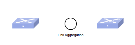
Link Aggregation increases link bandwidth, enables load sharing of traffic and improves link reliability by aggregating multiple physical links together to form a single logical link. As shown below, Device A and Device B are connected by three physical links, which are bundled into one logical link with a maximum bandwidth equal to the total bandwidth of the three physical links. At the same time, the three physical links are backed up by each other, so that when one of the links goes down, the other two links can still work.
Basic Concepts
Section titled “Basic Concepts”Aggregation Group and Member Port
Section titled “Aggregation Group and Member Port”Multiple ports are aggregated to form an aggregation group and these ports are called member ports of that aggregation group. Each aggregation group uniquely corresponds to a logical interface, called link aggregation interface. Aggregation group and link aggregation interface are numbered consistently.
hint{type=“warning”} NOTE: The aggregation group mode, system LACP priority, and load balancing algorithm must be configured when creating the LAG. If the LAG has Layer 2 or Layer 3 configurations or contains member ports, these configurations should be removed before modifying the attributes.
Set the IP Address for LAGIF
Section titled “Set the IP Address for LAGIF”Table 16 Set the IP Address for LAGIF
| Purpose | Commands | Description |
|---|---|---|
| Enter global configuration view | configure terminal | - |
| Enter LAG interface configuration view | interface link-aggregation lag-id | Aggregate group id, range 1-9999 |
| Set the IP address of the LAG interface | ip address {A.B.C.D/M|A::B/M} | IPv4 address with subnet mask /32 is not allowed to be configured. Addresses with subnet mask /31 is allowed. In other subnet masks, addresses with the host portion all-zeros or all-ones are not allowed.IPv6 address with subnet mask /127 or /128 is not allowed to be configured. In other subnet masks, addresses with the host portion all-zeros are not allowed, but all-ones are allowed. |
Configure MTU for LAGIF
Section titled “Configure MTU for LAGIF”Table 17 Configure the MTU for LAGIF
| Purpose | Commands | Description |
|---|---|---|
| Enter global configuration view | configure terminal | - |
| Enter LAG interface configuration view | interface link-aggregation lag-id | Aggregate group id, range 1-9999 |
| Configure the MTU of the LAG interface | mtu mtu | MTU range: 1312 to 9216 |
Configure MAC Address for LAGIF
Section titled “Configure MAC Address for LAGIF”By default, the MAC address of the interface is dynamically assigned by the system or is the same as the MAC address of the switch. This series supports users to reconfigure the MAC of physical interfaces, VLAN interfaces and link aggregated interfaces.
Table 18 Configure MAC Address for LAGIF
| Purpose | Commands | Description |
|---|---|---|
| Enter global configuration view | configure terminal | - |
| Enter LAG interface configuration view | interface link-aggregation lag-id | Aggregate group id, range 1-9999 |
| Configure the MAC address of LAGIF | mac-address HH:HH:HH:HH:HH:HH | MAC addresses are not case-sensitive |
| Restore the MAC address of LAGIF to its default value | no mac-address | - |
Shutdown the LAGIF
Section titled “Shutdown the LAGIF”Shutting down the aggregation port will cause all selected ports in the group to become unselected ports and the state of all member ports to change to down.
Table 19 Shutdown the LAGIF
| Purpose | Commands | Description |
|---|---|---|
| Enter global configuration view | configure terminal | - |
| Enter LAG interface configuration view | interface link-aggregation lag-id | Aggregate group id, range 1-9999 |
| Close the aggregation interface | shutdown | - |
| Opening the aggregation interface | no shutdown | - |
Display and Maintenance
Section titled “Display and Maintenance”Check the current aggregation group configuration status, display the protocol of each aggregation group of the system and ports in it.
Table 20 LAG Display and Maintenance
| Purpose | Commands | Description |
|---|---|---|
| Display aggregation group related information | show link-aggregation summary | - |
Abbreviations in table description: A - Active, I - InActive, Up - up, Dw - Down, N/A - not available, S - selected, D - deselected
Example.
sonic# show link-aggregation summaryFlags: A - Active, I - inActive, Up - up, Dw - Down, N/A - not available, S - selected, D - deselected, \* - not synced No. Team Dev Protocol Ports----- --------------- --------------- -----------------------------0001 PortChannel0001 LACP(A)(Dw) Ethernet46(D)0002 PortChannel0002 LACP(A)(Dw) N/A0100 PortChannel0100 LOADBALANCE(Up) Ethernet28(up)0101 PortChannel0101 LOADBALANCE(Up) Ethernet41(dw) Ethernet40(up)In the example, we can see that the third column of Protocol is identified as LACP or LOADBALANCE, when it is “LACP”, it means that member ports are added and removed dynamically via lacp, and the addition and deletion of member ports to the chip follows the 802.1ax protocol. When it is “LOADBALANCE”, it means static lag configuration, and the addition and deletion of member ports to the chip is directly dependent on manual configuration.
- When Protocol is in LACP mode, two attributes will be available: the LACP operating mode and the port status.
- LACP working mode has two states, I and A. A means Active mode and I means Inactive mode. For normal use, the Active mode is not provided for the configuration interface, and Active mode is used by default.
- The other attribute indicates the port status (Up/Dw), with Up indicating that the lag is functional and Dw indicating that the lag port is not forwarding traffic properly.
- The member port under the LACP protocol has a status attribute (S/S*/D). Only when it is S does it mean that the interaction with the peer is successful and the member port is correctly sent down to the chip. The rest of the states are not working properly: when it is S*, it is most likely that there is a mismatch between the local and the peer information; when it is D, it is likely that no LACPDU packet has been received, that is, the peer has not configured the lag. In the dynamic LAG only if the number of the member port in the S state is not less than min-links, the lag will be in the up state and can participate in forwarding.
- When Protocol is LOADBALANCE mode, there is only one port status attribute. This attribute is actually the link state of the port.
- When the port link status is up, it means the port is working normally, and it is added to the portchannel as a member port in the chip, and can participate in the forwarding of the portchannel.
- When the port link status is down, it means that the port is working down and not added to the LAG.
Typical Configuration Example
Section titled “Typical Configuration Example”Layer 2 Static Aggregation
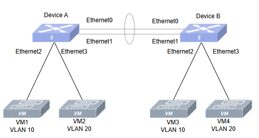
Section titled “Layer 2 Static Aggregation”- Networking Requirements Device A and Device B are connected to each other via their respective Ethernet0, 1. Configure a Layer 2 static link aggregation group on Device A and Device B and implement separate interworking of VMs in VLAN 10 and VLAN 20.
- Topology
- Procedure
Device A
#Create VLAN10 and add Ethernet2 to this VLAN.
sonic# configure terminalsonic(config)# vlan 10sonic(config-vlan-10)# exsonic(config)# interface ethernet 0/2sonic(config-if-0/2)# switchport access vlan 10sonic(config-if-0/2)# ex#Create VLAN 20 and add Ethernet3 to this VLAN.
sonic(config)# vlan 20sonic(config-vlan-20)# exsonic(config)# interface ethernet 0/3sonic(config-if-0/3)# switchport access vlan 20sonic(config-if-0/3)# ex#Create static aggregation port Lag1 and add Ethernet0, 1 to this aggregation group.
sonic(config)# interface link-aggregation 1sonic(config-lagif-1)# mode staticsonic(config-lagif-1)# commitsonic(config-lagif-1)# exsonic(config)# interface ethernet 0/0sonic(config-if-0/0)# link-aggregation-group 1sonic(config-if-0/0)# exsonic(config)# interface ethernet 0/1sonic(config-if-0/1)# link-aggregation-group 1sonic(config-if-0/1)# ex#Add Lag1 to VLAN10, 20.
sonic(config)# interface link-aggregation 1sonic(config-lagif-1)# switchport trunk vlan 10sonic(config-lagif-1)# switchport trunk vlan 20Device B Similar to Device A, the configuration process is skipped.
- Verify the configuration.
show link-aggregation summaryThe VMs in Vlan10 and Vlan20 ping each other separately and can ping through.
Layer 2 Dynamic Aggregation
Section titled “Layer 2 Dynamic Aggregation”- Networking Requirements
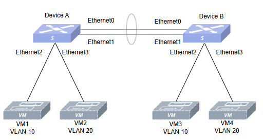
Device A and Device B are connected to each other via their respective Ethernet0, 1. Configure a Layer 2 dynamic link aggregation group on Device A and Device B and implement separate interworking of VMs in VLAN 10 and VLAN 20.
- Topology
- Procedure
Device A #Create VLAN10 and add Ethernet2 to this VLAN.
sonic# configure terminalsonic(config)# vlan 10sonic(config-vlan-10)# exsonic(config)# interface ethernet 0/2sonic(config-if-0/2)# switchport access vlan 10sonic(config-if-0/2)# ex#Create VLAN 20 and add Ethernet3 to this VLAN.
sonic(config)# vlan 20sonic(config-vlan-20)# exsonic(config)# interface ethernet 0/3sonic(config-if-0/3)# switchport access vlan 20sonic(config-if-0/3)# ex#Create dynamic aggregation port Lag1 and add Ethernet0, 1 to this aggregation group.
sonic(config)# interface link-aggregation 1sonic(config-lagif-1)# mode dynamicsonic(config-lagif-1)# commitsonic(config-lagif-1)# exsonic(config)# interface ethernet 0/0sonic(config-if-0/0)# link-aggregation-group 1sonic(config-if-0/0)# exsonic(config)# interface ethernet 0/1sonic(config-if-0/1)# link-aggregation-group 1sonic(config-if-0/1)# ex#Add PortChannel0001 to VLANs 10 and 20.
sonic(config)# interface link-aggregation 1sonic(config-lagif-1)# switchport trunk vlan 10sonic(config-lagif-1)# switchport trunk vlan 20Device B
Similar to Device A, the configuration process is skipped.
- Verify the configuration.
show link-aggregation summaryThe VMs in Vlan10 and Vlan20 ping each other separately and can ping through.
Layer 3 Static Aggregation
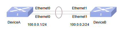
Section titled “Layer 3 Static Aggregation”- Networking Requirements Device A and Device B are connected to each other via their respective Ethernet0, 1. Configure a Layer 3 static link aggregation group with IP on Device A and Device B respectively.
- Topology
- Procedure
Device A #Create static aggregation port Lag1 and add Ethernet0, 1 to this aggregation group.
sonic(config)# interface link-aggregation 1sonic(config-lagif-1)# mode staticsonic(config-lagif-1)# commitsonic(config-lagif-1)# exsonic(config)# interface ethernet 0/0sonic(config-if-0/0)# link-aggregation-group 1sonic(config-if-0/0)# exsonic(config)# interface ethernet 0/1sonic(config-if-0/1)# link-aggregation-group 1sonic(config-if-0/1)# ex#Set the IP for Lag1.
sonic(config)# interface link-aggregation 1sonic(config-lagif-1)# ip address 100.0.0.1/24Device B
Similar to Device A, the configuration process is skipped. 4. Verify the configuration.
show link-aggregation summaryDevice A pinging Device B can ping through.
Layer 3 Dynamic Aggregation
Section titled “Layer 3 Dynamic Aggregation”- Networking Requirements Device A and Device B are connected to each other via their respective Ethernet0, 1. Configure a Layer 3 dynamic link aggregation group with IPs on Device A and Device B respectively, and require a short timeout for LACP.
- Topology
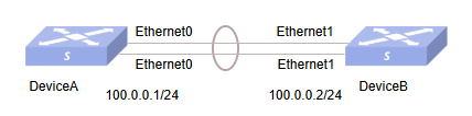
- Procedure
Device A
#Create dynamic aggregation port Lag1 and add Ethernet0, 1 to this aggregation group.
sonic(config)# interface link-aggregation 1sonic(config-lagif-1)# mode dynamicsonic(config-lagif-1)# commitsonic(config-lagif-1)# lacp fast-ratesonic(config-lagif-1)# commitsonic(config-lagif-1)# exsonic(config)# interface ethernet 0/0sonic(config-if-0/0)# link-aggregation-group 1sonic(config-if-0/0)# exsonic(config)# interface ethernet 0/1sonic(config-if-0/1)# link-aggregation-group 1sonic(config-if-0/1)# ex#Set the IP for Lag1.
sonic(config)# interface link-aggregation 1sonic(config-lagif-1)# ip address 100.0.0.1/24Device B
Similar to Device A, the configuration process is skipped. 4. Verify the configuration.
show link-aggregation summaryDevice A pinging Device B can ping through.