


QoS Configuration Guide
此内容尚不支持你的语言。
QoS (Quality of Service) is a technique used to solve problems such as network latency and blocking. As a security mechanism in a network, QoS can provide better service capability and improved quality of service for specified network communications. Under normal circumstances, QoS is not required if the network is only used for specific untime-limited applications, such as web applications, or e-mail settings. But for critical applications and multimedia applications it is essential that QoS ensures that critical traffic is not delayed or dropped when the network is overloaded or congested, and that the network operates efficiently.
Concepts and Principles
Section titled “Concepts and Principles”Queue and Priority Mapping
Section titled “Queue and Priority Mapping”Different messages use different QoS priorities, for example, 802.1p for VLAN messages, DSCP for IP messages, TC for IPv6 messages, EXP for MPLS messages. In order to ensure the quality of service of different messages, when the message comes into the switch, the QoS priority carried by the message needs to be mapped to the internal service class (also called scheduling priority PHB) and discard priority (also called color) of the switch. Inside the switch, congestion management is carried out according to the class of service of the message and congestion avoidance according to the color of the message; when the message leaves the switch, the internal class of service and color need to be mapped to QoS priority so that subsequent network devices can provide the appropriate quality of service according to the QoS priority. Generally, the PHB ranges from 0 to 7, or is indicated by BE, AF1, AF2, AF3, AF4, CS6, CS7 respectively, and Color is available in green, yellow and red. Two types of message fields related to QoS priority are listed below.
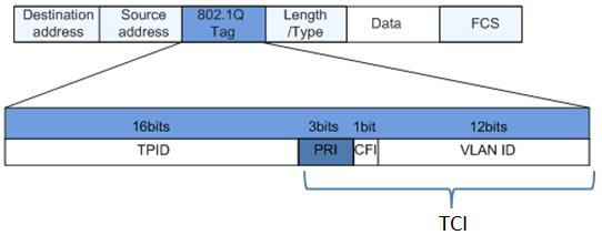
- Priority in Layer 2 VLAN frames The priority in a Layer 2 frame is specific to VLAN frames, as ordinary Layer 2 frames do not carry a priority field. The priority in a VLAN frame is what is commonly referred to as the 802.1p priority (defined by the IEEE 802.1p protocol), and is located in the “PRI” subfield of the “802.1Q Tag” field in the VLAN frame, as shown in the figure below. The PRI field is 3 bits long and can represent 8 transmission priorities, with values of 7, 6, …, 1, 0 in descending order of priority. The different priority levels identify the different levels of quality of service required.
- Priority in Layer 3 IP messages The Layer 2 VLAN frame priority described above is relatively simple, but in Layer 3 IP messages the description of priority is much more complex, and two different types of priority and different methods of identification have emerged at different times.
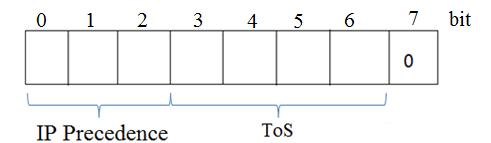
- ToS In the early RFC 791 standard, IP packets relied on the ToS (Type of Service) field to identify the data priority value, which is a field (1 byte in total) in the IP header of an IP packet that specifies the priority of the IP packet, and the switch preferentially forwards packets with a high ToS value. It contains a byte (8 bits) and consists of three parts: three bits from 0 to 2 to define the IP priority of the packet (IP Precedence), ToS and the last bit fixed to 0, as shown in the figure.
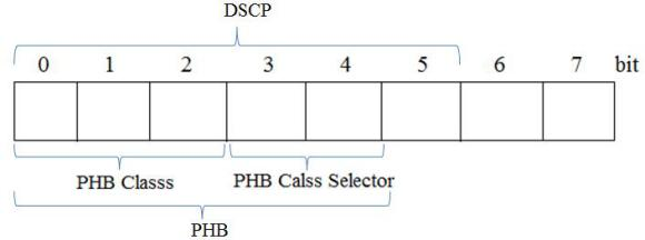
- DSCP In the later new RFC 2474 standard, the ToS field in the original IP packet header was redefined and renamed the DS (Differentiated Services) field, which is also a total of one byte (8 bits). In general, bits 0 to 5 (six bits in total) are used to indicate the DSCP (Differentiated Services Code Point) priority, with values ranging from 0 to 63, which identifies a total of 64 priority values (the higher the value, the higher the priority), and the last two bits are reserved to display the ECN (Explicit Congestion Notification).
Flow Shape
Section titled “Flow Shape”Congestion in the network may be caused when the rate at which messages are sent is greater than the rate at which they are received, or when the interface rate of a downstream device is less than the interface rate of an upstream device. If the size of the service traffic sent by users is not limited, the constant burst of service data from a large number of users will make the network more congested. In order to make the limited network resources more efficient for the users, it is necessary to limit the service traffic of the users. Flow shaping provides the possibility to control the maximum output communication rate to ensure that communication meets the configured maximum transmission rate specification. Traffic shaping is usually done using buffers and token buckets. When messages are sent at too fast a rate, they are first cached in the buffers and these buffered messages are then sent evenly under the control of the token buckets. When the interface rate of the downstream device is less than the port rate of the upstream device or when burst traffic occurs, traffic congestion may occur at the incoming port of the downstream device. In this case, the user can configure traffic shaping on the outgoing port of the upstream device to cut the upstream irregular traffic and output a flatter traffic, thus solving the congestion problem of the downstream device. There are two types of flow shaping.
- Interface traffic shaping Interface traffic shaping, also known as interface rate limiting LR (Line rate), limits the total rate of all messages (including emergency messages) sent by the interface and is traffic shaping for the entire outgoing interface, regardless of priority.
- Queue traffic shaping Queue traffic shaping, also known as Shaping, allows traffic to be shaped for a particular queue on the outgoing interface, with differentiated priority. Each of the two traffic shaping methods has its own advantages and can be applied for different demand scenarios. Users can choose according to their scenarios and needs.
Congestion Management and Congestion Avoidance
Section titled “Congestion Management and Congestion Avoidance”The quality of service problems faced by traditional networks are mainly caused by congestion, which refers to problems that occur when multiple users compete for the same resources (bandwidth, buffers, etc.) on a shared network.
- Congestion Management Congestion Management is a traffic control mechanism to meet the high QoS service of delay-sensitive services by adjusting the scheduling order of messages when the network is intermittently congested and the delay-sensitive services require a higher quality QoS service than other services. This is handled by using queuing techniques, where all messages from a port are placed into multiple queues and processed according to queue priority. Queue refers to the logic of sorting messages in the cache. When the rate of traffic exceeds the interface bandwidth or the bandwidth set for that traffic, the messages are temporarily stored in the cache in a queue. The processing order and discard principle for message forwarding is determined by the queue scheduling algorithm. This series of switches supports PQ, DWRR and hybrid scheduling modes, which are described below.
- PQ Dispatch PQ (Priority Queuing) scheduling, also known as SP (Strict Priority), refers to the scheduling of queues in strict order of priority. Only after all messages in the high priority queue have been scheduled will the lower priority queue have a chance to be scheduled. PQ scheduling is used to place delay-sensitive critical services into a high-priority queue and non-critical services into a low-priority queue, thus ensuring that critical services are sent first. Disadvantage of PQ scheduling: when congestion occurs, messages in the lower priority queues will not get a chance to be scheduled if the higher priority queues are occupied for a long time.
- DWRR Dispatch Understanding DWR (Deficit Weighted Round Robin) scheduling begins with WRR (Weighted Round Robin) scheduling, which rotates between queues to ensure that each queue receives a certain amount of service time. Using the example of a port with 8 output queues, WRR can configure a weighting value for each queue (w7, w6, w5, w4, w3, w2, w1, w0 in that order), with the weighting value indicating the weight of the acquired resources. Example a 100M port is configured with a weighting value of 50, 50, 30, 30, 10, 10, 10, 10, 10 (corresponding to w7, w6, w5, w4, w3, w2, w1, w0 in that order) for its WRR queue scheduling algorithm, which ensures that the lowest priority queue gets at least 5Mbit/s of bandwidth, avoiding the disadvantage that messages in the low priority queue may go unserved for a long time when PQ scheduling is used. Disadvantages of WRR scheduling: WRR scheduling is based on the number of messages, so there is no fixed bandwidth per queue, and the actual bandwidth obtained by a larger message is greater than that obtained by a smaller message for the same scheduling opportunity. And it is bandwidth that users are generally concerned about. When the average message length of each queue is equal or known, the user can obtain the desired bandwidth by configuring the WRR weight; however, when the average message length of the queue varies, the user cannot obtain the desired bandwidth by configuring the WRR weight. Another disadvantage is that low latency demand services (e.g. voice) are not scheduled in a timely manner. DWRR, or differential weighted polling, is implemented on the same principle as WRR scheduling, but DWRR is able to schedule messages according to their length, avoiding the disadvantage that WRR scheduling cannot allocate bandwidth resources in proportion to the configuration. DWRR also has the disadvantage that delay-sensitive services (such as voice) are not scheduled in a timely manner.
- Hybrid scheduling PQ scheduling and DWRR scheduling have their own advantages and disadvantages. When PQ scheduling is used alone, messages in the low priority queue may not be scheduled for a long time, while when DWRR scheduling is used alone, low latency demand services are not scheduled timely. The “PQ+DWRR” scheduling method combines the advantages of both scheduling methods and overcomes the disadvantages of each. Users can place important protocol messages and delay-sensitive service messages into the queue using PQ scheduling and assign a designated bandwidth to this queue, while other messages are placed into each queue using DWRR scheduling according to their respective priorities, and each queue is scheduled cyclically according to its weight.
hint{type=“warning”} NOTES:
- DSCP and DOT1P priority mapping cannot be configured at the same time.
- tc takes values from 0 to 7, out of range it may not be able to forward messages or be able to default to queue0 forwarding, this behaviour varies from chip to chip. the behaviour of Innovium chips is forwarding.
- Priority configuration at the traffic ingress, role at the traffic egress.
Configure DSCP to COS Mapping
Table 3 Configure DSCP to COS Mapping
| Operation | Commands | Description |
|---|---|---|
| Enter global configuration view | configure terminal | - |
| Create a Diffserv Map map and enter its configuration view | diffserv-map type ip-dscp diffserv-map-name | diffserv-map-name: name of diffserv-map |
| Configure DSCP to COS mapping | ip-dscp value cos cos_value | value: DSCP value, range 0-63 cos_value: COS value, range 0-7 |
| default {cos_value|copy} | cos_value indicates that all packets are mapped to the corresponding COS value. default copy indicates to use the default DSCP mapping of the system. | |
| Exit Diffserv Map view | exit | - |
| Create a policy-map and enter its configuration view | policy-map policy-map-name | - |
| Configure DSCP to TC mapping | set cos dscp diffserv diffserv-map-name | - |
| Exit Policy Map view | exit | - |
| Enter interface configuration view | interface ethernet interface-name | - |
| Bind policies to interfaces | service-policy policy-map-name | Bind the interface will make the policy effective, the policy configuration cannot be modified at this time |
Configure DOT1P to COS Mapping
Table 4 Configure DOT1P to COS Mapping
| Operation | Commands | Description |
|---|---|---|
| Enter global configuration view | configure terminal | - |
| Create a Diffserv Map map and enter its configuration view | diffserv-map type ip-8021p diffserv-map-name | diffserv-map-name: name of diffserv-map |
| Configure dot1p to cos mapping | 8021p value cos cos-value | value: DOT1P value, range 0-7 cos-value: cos value, range 0-7 |
| default value | All unconfigured packets are marked with the cos value. value: cos value (0-7) | |
| Exit Diffserv Map view | exit | - |
| Create a policy-map and enter its configuration view | policy-map policy-map-name | policy-map-name: the name of the policy-map |
| Configure dot1p to tc mapping | set cos 8021p diffserv diffserv-map-name | - |
| Exit Policy Map view | exit | - |
| Enter interface configuration view | interface ethernet interface-name | - |
| Bind policies to interfaces | service-policy policy-map-name | Bind the interface will make the policy effective, the policy configuration cannot be modified at this time |
Configure QoS Schedule Policy
Section titled “Configure QoS Schedule Policy”hint{type=“info”} NOTE: Traffic shaping policy is currently only supported on egress port of the traffic.
Configure Port Speed Limit
Table 7 Configure Port Speed Limit
| Purpose | Commands | Description |
|---|---|---|
| Enter global configuration view | configure terminal | - |
| Create a policy-map and enter its configuration view | policy-map policy-map-name | - |
| Configure port speed limit policy | port-shape target-bit-rate [burst-size] | target-bit-rate: peak speed limit value (byte/s).burst-size: peak burst value (byte) |
| Enter interface configuration view | interface ethernet interface-name | - |
| Bind policy to interface | service-policy policy-map-name | Binding the interface will make the policy effective, the policy configuration cannot be modified at this time |
Configure Queue Speed Limit
Table 8 Configure Queue Speed Limit
| Purpose | Commands | Description |
|---|---|---|
| Enter global configuration view | configure terminal | - |
| Create a Class Map and enter its configuration view | class-map class-map-name | - |
| Specify the queue for speed limit | match cos queue | The value of queue is 0-7, use space to separate multiple queues. |
| Exit Class-map configuration view | exit | - |
| Create a policy-map and enter its configuration view | policy-map policy-map-name | - |
| Bind the class-map and enter the policy class-map configuration view | class class-map-name | This command is executed in Policy Map view |
| Configure queue speed limit policy | queue-shape target-bit-rate [burst-size] | The configured queue determined by class-map.target-bit-rat specifies the peak speed limit value in bits/s.burst-size specifies the burst value in bits |
| Exit Class view under Policy Map | exit | - |
| Exit Policy Map configuration view | exit | - |
| Enter Ethernet interface view | interface ethernet interface-name | - |
| Bind policy to interface | service-policy policy-map-name | Binding the interface will make the policy effective, the policy configuration cannot be modified at this time, it needs to be modified after unbinding |
Configure PFC
Section titled “Configure PFC”The port can receive PFC PAUSE frames regardless of whether the port is configured with the PFC function or not. However, the received PFC PAUSE frames are only processed when the PFC function is on. Therefore, it is necessary to ensure that the PFC function is on at both the local end and the other end in order for the PFC function to take effect. In order to avoid packet loss due to congestion during transmission, please configure the same PFC function on all ports through which the message flows. The ingress buffer of the switch chip is shared by all ports, but can be allocated in flow control scenarios. When not configured by the user, the default trigger threshold and stop threshold values for backpressure frames in the ingress direction is present in the interface configuration. The default setting can be viewed by the show buffer profile command. the default parameter set works better in a general networking environment. In order to control the PFC function flexibly and use the interface storage space reasonably, the switch provides PFC waterline configuration and supports user-defined configuration of the PFC buffer profile, including enable queue, configure buffer size, trigger high and low thresholds for PAUSE frames.
hint{type=“success”} NOTES:
- By default, queues 3 and 4 of all ports are lossless queues with PFC-enabled, and the rest of the queues are PFC-disabled.
- Currently, the queue enable/disable PFC control object is all interfaces, and there is no interface switch for the time being.
- Supports up to two queues to enable PFC.
Table 9 Global Enable PFC
| Purpose | Commands | Description |
|---|---|---|
| Enter global configuration view | configure terminal | - |
| Enable PFC | priority-flow-control enable ingress-queue | ingress-queue: indicates a queue, range 0-7. You can specify a queue (eg: 1) or specify some queues (eg: 1 4) |
| Save the configuration and reload to take effect. | writereload | - |
Table 10 Global Disable PFC
| Purpose | Commands | Description |
|---|---|---|
| Enter global configuration view | configure terminal | - |
| Disable PFC | no priority-flow-control enable ingress-queue-id | ingress-queue: indicates a queue, range 0-7. You can specify a queue (eg: 1) or specify some queues (eg: 1 4), |
| Save the configuration and reload to take effect. | writereload | - |
Configure the PFC Lossless Buffer
The cell size varies from model to model.
- On CX308P-48Y-N-V2 and CX532P-N-V2, cell size=128 Bytes. When a queue on the switch is congested and the occupancy of the ingress buffer reaches the waterline, it will start to send backpressure frames; when the sender receives the backpressure frames and reduces the sending traffic, the occupancy of the ingress buffer on the switch will decrease and stop sending backpressure frames when the occupancy is below the waterline; the formula of PFC waterline is: Limit=Guaranteed Buffers+Dynamic Factor (in static mode, Dynamic Factor is different).When using self-defined lossless buffers, it is recommended to configure static mode.
- On other models, cell size=224 Bytes. When a queue on the switch is congested and the occupancy of the ingress buffer reaches xoff, it starts to send backpressure frames; when the sender receives abackpressure frames and reduces the sending traffic, the occupancy of the ingress buffer of the switch will decrease and stop sending backpressure frames when the occupancy reaches xon. When the user does not configure it, default trigger thresholds and stop thresholds for backpressure frames in the inbound direction exist in the interface configuration. When using self-defined lossless buffers, it is recommended to configure static mode. The parameters of dynamic lossless buffer are related to the interface rate, cable length, etc., and the following are the recommended configuration values:
Table 11 Recommended Values
| rate | cable length | size | xon | xoff | dynamic threshold | xon_offset |
|---|---|---|---|---|---|---|
| 25000 | 5m | 1518 | 0 | 15680 | 1 | 13440 |
| 50000 | 5m | 1518 | 0 | 21248 | 1 | 13440 |
| 100000 | 5m | 1518 | 0 | 34624 | 1 | 13440 |
| 400000 | 5m | 1518 | 0 | 117536 | 1 | 13440 |
| 25000 | 40m | 1518 | 0 | 16928 | 1 | 13440 |
| 50000 | 40m | 1518 | 0 | 23392 | 1 | 13440 |
| 100000 | 40m | 1518 | 0 | 38816 | 1 | 13440 |
| 400000 | 40m | 1518 | 0 | 135520 | 1 | 13440 |
| 25000 | 100m | 1518 | 0 | 18848 | 1 | 13440 |
| 50000 | 100m | 1518 | 0 | 27264 | 1 | 13440 |
| 100000 | 100m | 1518 | 0 | 46496 | 1 | 13440 |
| 400000 | 100m | 1518 | 0 | 166688 | 1 | 13440 |
| 25000 | 300m | 1518 | 0 | 25184 | 1 | 13440 |
| 50000 | 300m | 1518 | 0 | 40128 | 1 | 13440 |
| 100000 | 300m | 1518 | 0 | 72384 | 1 | 13440 |
| 400000 | 300m | 1518 | 0 | 268640 | 1 | 13440 |
hint{type=“warning”} NOTES:
- WRED should be configured on the traffic egress.
- ECN marking function only works for TCP and UDP messages.
Configure WRED Dropp Profile
Table 15 Configure WRED Drop Profile
| Purpose | Commands | Description |
|---|---|---|
| Enter global configuration view | configure terminal | - |
| Create WRED profil and enter its configuration view | wred profile-name | profile-name: WRED profile name |
| Configure the WRED profile | mode drop gmin min_th gmax max_th gprobability probability [ymin min_th ymax max_th yprobability probability | rmin min_th rmax max_th rprobability probability] | - |
- min_th sets the lower absolute limit of WRED drop in bytes. That is, when the message length in the queue reaches this value, WRED drop starts. The configurable minimum value of min threshold is 15KB. The recommended configuration value is 15360.
- max_thsets the upper absolute value of WRED drop in bytes. That is, when the message length in the queue reaches this value, it starts to drop all newly received messages; for CX308P-48Y-N devices, the value range is min_th-25165824; for other models of devices, the value range is min_th-10243072. The recommended configuration values for the different rate interfaces are as follows: 25G(bps) ---192000(bytes) 100G(bps) --- 768000(bytes) 200G(bps) --- 768000(bytes) 400G(bps) --- 1536000(bytes)
- probabilitysets the maximum drop probability in the form of integer and the value range is [1,100]. For delay-sensitive services, it is recommended that the maximum drop probability be set to 90%; for throughput-sensitive services, it is recommended that it be set to 10%.
Configure Explicit Congestion Notification
Table 16 Configure Explicit Congestion Notification
| Purpose | Commands | Description |
|---|---|---|
| Enter global configuration view | configure terminal | - |
| Create a WRED and enter its configuration view | wred profile-name | - |
| Configure ECN parameters. | mode ecn gmin min_th gmax max_th gprobability probability [ymin min_th ymax max_th yprobability probability | rmin min_th rmax max_th rprobability probability] | - |
- min_th Set the low limit absolute value of ECN in bytes. When the message length in the queue reaches this value, the interface starts to set the ECN field of the message to CE according to the probability. The configurable minimum value is 15 KB.The recommended configuration value is 15360.
- max_thSet the high limit absolute value of ECN in bytes. When the message length in the queue reaches this value, the interface starts to set ECN field of all packets to CE. For CX308P-48Y-N-V2 and CX532P-N-V2 , the range is min_th - 25165824, and for other models, the range is min_th - 10243072. The recommended configuration values for the different rate interfaces are as follows: 25G(bps) ---192000(bytes) 100G(bps) --- 768000(bytes) 200G(bps) --- 768000(bytes) 400G(bps) --- 1536000(bytes)
- probability Set the maximum mark probability in integer form. The range is [1,100]. It is recommended to set the mark probability to 90 percent for latency-sensitive services and 10 percent for throughput-sensitive services.
Apply the WRED Profile
After configuring a WRED drop policy or ECN policy, you need to bind interfaces and queues for it to take effect.
Table 17 Apply the WRED Profile
| Purpose | Commands | Description |
|---|---|---|
| Enter global configuration view | configure terminal | - |
| Create a Class Map and enter its configuration view | class-map class-map-name | - |
| Specify the queue for which WRED is applied | match cos queue | The value of queue is 0-7, use space to separate multiple queues. |
| Exit Class-map configuration view | exit | - |
| Enter Policy Map view | policy-map policy-map-name | - |
| Bind the class-map | class class-map-name | - |
| Policy binds WRED profile | wred profile-name | - |
| Exit the Class view under Policy Map | exit | - |
| Exit Policy Map view | exit | - |
| Enter Ethernet interface view | interface ethernet interface-name | - |
| Bind policy to interface | service-policy policy-map-name | After the policy is bound to interface , dynamic modification of the policy configuration is not allowed. |
Configure Packet Remarking
Section titled “Configure Packet Remarking”Table 18 Configure Packet Remarking
| Purpose | Commands | Description |
|---|---|---|
| Enter global configuration view | configure terminal | - |
| Create Layer 3 ACL table | access-list table_name l3 {ingress | egress} | - |
| Bind interface | bind interface {ethernet interface-name | link-aggregation lag-id |all} | - |
| Configure remarking rule | rule rule-id rule_options {set-dscp dscp | set-tc tc |set-pcp pcp} | rule-id: Rule sequence number (Range: 1–500)rule_options: match fields.set-dscp: Modify DSCP value (dscp: 0–63)set-tc: Modify CoS value (tc: 0–7)set-pcp: Modify VLAN priority (pcp: 0–7) |
Display and Maintenance
Section titled “Display and Maintenance”Class Map Information
Section titled “Class Map Information”Table 19 Class Map Information View
| Purpose | Commands | Description |
|---|---|---|
| Show class map configuration | show class-map class-map-name |
Diffserv Map Information
Section titled “Diffserv Map Information”Table 20 Diffserv Map Information View
| Purpose | Commands | Description |
|---|---|---|
| Show Diffserv Map configuration | show diffserv-map [type {ip-dscp {default | diffserv_map_name}|8021p diffserv_map_name}] | - |
Policy Map Information
Section titled “Policy Map Information”Tables 21 PFC Information View
| Purpose | Commands | Description |
|---|---|---|
| Show Policy Map information | show policy-map | - |
PFC Information
Section titled “PFC Information”Table 22 PFC Information View
| Purpose | Commands | Description |
|---|---|---|
| Show all interface PFC modes | show interface priority-flow-control | - |
| Show PFC buffer profile configuration | show buffer profile | - |
| Show PFC profile configuration | show pfc profiles | |
| Show PFC count | show counters priority-flow-control | - |
| Clear PFC count | clear counters priority-flow-control | - |
PFCWD Information
Section titled “PFCWD Information”Table 23 PFCWD Information View
| Purpose | Commands | Description |
|---|---|---|
| Display PFCWD configuration | show pfcwd configuration | - |
| Display PFCWD statistic information | show pfcwd stats | - |
WRED Information
Section titled “WRED Information”Table 24 WRED Information View
| Purpose | Commands | Description |
|---|---|---|
| Show wred profile configuration | show wred profile-name | - |
| Show the ECN enable status of an interface | show interface ecn {detail} | - |
| Show ECN count | show counters ecn | CX308P-48Y-N-V2 and CX532P-N-V2 are not supported now. |
| Clear ECN count | clear counters ecn | - |
| ECN buffer usage view | show counters ecn-buffer interface interface_name queue queue-id | queue-id: queue ID.Not supported by CX308P-48Y-N-V2 and CX532P-N-V2 |
Queue Information
Section titled “Queue Information”Table 25 Queue Information View
| Purpose | Commands | Description |
|---|---|---|
| Show queue count | show counters queue [interface-name] | - |
| Clear queue count | clear counters queue | - |
Typical Configuration Example
Section titled “Typical Configuration Example”Example of Priority Mapping and Queue Scheduling Configuration
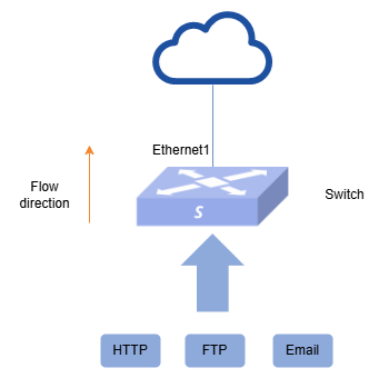
Section titled “Example of Priority Mapping and Queue Scheduling Configuration”- Network Requirements The network structure of a data center is shown in the figure below. There are three types of traffic accessing the Internet in the network: HTTP, FTP and Email, and the DSCP bits in the corresponding messages are 33, 35 and 27 respectively. The following requirements are required: Set the packet transmission priority on the Switch as follows: HTTP>FTP>Email. When congestion occurs, priority will be given to the transmission of HTTP messages, and HTTP data must be sent first before other data is sent, and the ratio of FTP to Email traffic will be 2:1.
- Topology
- Procedure
- Configure each interface IP to enable users to access the network through the Switch. (skipped)
- Check the default mapping relationship on the port and find that dscp33, 35 and 27 are mapped to local priority 0. According to the networking requirements, these three types of messages should be mapped to different queues. Here, dscp33, 35 and 27 are mapped to queues 5, 6 and 7 respectively as an example.
sonic# configure terminal sonic(config)# diffserv-map type ip-dscp dscp-profile sonic(config-diffservmap-dscp-profile)# ip-dscp 33 cos 5 sonic(config-diffservmap-dscp-profile)# ip-dscp 35 cos 6 sonic(config-diffservmap-dscp-profile)# ip-dscp 27 cos 7 sonic(config-diffservmap-dscp-profile)# exit sonic(config)# policy-map pmap1 sonic(config-pmap-pmap1)# set cos dscp diffserv dscp-profile sonic(config-pmap-pmap1)# exit sonic(config)# interface ethernet 0/0 sonic(config-if-0/1)# service-policy pmap1- Configure DWRR+SP schedule on switch Ethernet1.
sonic(config)# policy-map pmap2 sonic(config-pmap-pmap2)# queue-scheduler queue-limit percent 20 queue 6 sonic(config-pmap-pmap2)# queue-scheduler queue-limit percent 10 queue 7 sonic(config-pmap-pmap2)# queue-scheduler priority queue 5 sonic(config)# interface ethernet 0/1 sonic(config-if-0/1)# service-policy pmap2- Verify
- Verify the configuration
sonic# show diffserv-map type ip-dscp dscp-profileDiffserv Map dscp-profile:Type ip-dscp from 27 to 7 from 33 to 5 from 35 to 6sonic# show policy-map!policy-map pmap1set cos dscp diffserv dscp-profile!policy-map pmap2queue-scheduler priority queue 5queue-scheduler queue-limit percent 10 queue 7queue-scheduler queue-limit percent 20 queue 6sonic# show interface policy-mapPort service policy------ ---------------0/0 pmap10/1 pmap2- Send the stream to verify. Check queue reception on switch port Ethernet1.
sonic# show counters queue 0/1When congestion occurs, traffic on queue5 is sent first and there is no packet loss. queue6 and 7 both experience packet loss and transmit traffic in a ratio of roughly 2:1.
Example of Flow Shape Configuration
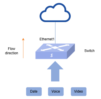
Section titled “Example of Flow Shape Configuration”- Networking Requirements The network structure of a data center is shown in the figure below. The services from the network side of the group are data, voice and video, carrying 802.1p priorities of 2, 5 and 6 respectively. Bandwidth jitter may occur as the traffic rate on the ingress side of the Switch is greater than the rate on the egress side. In order to reduce bandwidth jitter while ensuring bandwidth requirements for all types of services, it is required that
- Switch egress bandwidth limited to 1000Mbit/s.
- Data bandwidth limited to 200Mbit/s.
- Voice bandwidth limited to 300Mbit/s.
- Video bandwidth limited to 500Mbit/s.
- Topology
- Procedure
- Configure each interface IP to enable users to access the network through the Switch. (skipped)
- Configure the priority mapping of dot1p_to_tc.
sonic# configure terminalsonic(config)# diffserv-map type ip-dscp dscp-profilesonic(config-diffservmap-dscp-profile)# ip-dscp 2 cos 2sonic(config-diffservmap-dscp-profile)# ip-dscp 5 cos 5sonic(config-diffservmap-dscp-profile)# ip-dscp 6 cos 6sonic(config-diffservmap-dscp-profile)# exitsonic(config)# policy-map pmap1sonic(config-pmap-pmap1)# set cos dscp diffserv dscp-profilesonic(config-pmap-pmap1)# exitsonic(config)# interface ethernet 0/0sonic(config-if-0/1)# service-policy pmap1- Configure port traffic shaping and queue traffic shaping on Ethernet1 of the Switch. Set pir=1000Mb/s and pbs=1280000b.
sonic(config)# class-map que2sonic(config-cmap-c1)# match cos 2sonic(config)# class-map que5sonic(config-cmap-c1)# match cos 5sonic(config)# class-map que6sonic(config-cmap-c1)# match cos 6sonic(config)# policy-map pmap2sonic(config-pmap-pmap2)# port-shape 1000000000 1280000sonic(config-pmap-pmap2)# queue-scheduler priority queue 2sonic(config-pmap-pmap2)# queue-scheduler priority queue 5sonic(config-pmap-pmap2)# queue-scheduler priority queue 6sonic(config-pmap-pmap2)# class que2sonic(config-pmap-c)# queue-shape 200000000 256000sonic(config-pmap-c)# exitsonic(config-pmap-pmap1)# class que5sonic(config-pmap-c)# queue-shape 500000000 640000sonic(config-pmap-c)# exitsonic(config-pmap-pmap2)# class que6sonic(config-pmap-c)# queue-shape 600000000 768000sonic(config-pmap-c)# endsonic# configure terminalsonic(config)# interface ethernet 0/1sonic(config-if-0/1)# service-policy pmap2- Verify
- Verify the configuration
sonic# show diffserv-map type ip-dscp dscp-profileDiffserv Map dscp-profile:Type ip-dscp from 2 to 2 from 5 to 5 from 6 to 6sonic# show policy-map!policy-map pmap1set cos dscp diffserv dscp-profile!policy-map pmap2class que2 queue-shape 200000000 256000class que5 queue-shape 500000000 640000class que6 queue-shape 600000000 768000port-shape 1000000000 1280000queue-scheduler priority queue 2queue-scheduler priority queue 5queue-scheduler priority queue 6sonic# show interface policy-mapPort service policy------ ---------------0/0 pmap10/1 pmap2- Send the stream to verify. Check the port count and queue count, and both meet the requirements.
show counters interfaceshow counters queue 0/1