


Switch Configuration
此内容尚不支持你的语言。
Users need to configure the service vlans and IP gateways required for the switch in the switch configuration section, and configure the DHCP server or specify the IP address of the DHCP server. Multiple business vlans can be added as needed to handle different business requirements.
Small/Mid-Scale Campus
Section titled “Small/Mid-Scale Campus”For Small/Mid-Scale Campus, business gateways are distributed and deployed on Leaf switches at each access layer. Users only need to create wired business configurations on the Leaf.
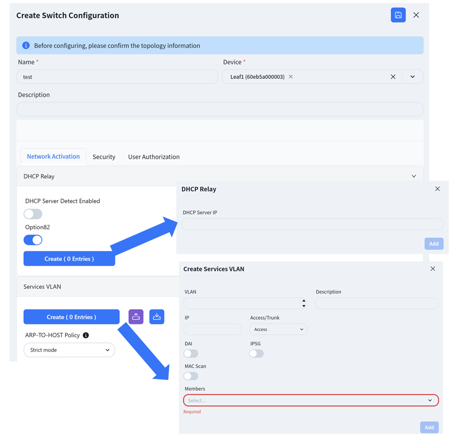
- [DHCP Relay]: Configure the DHCP server IP address. When the DHCP server does not support recognizing the option82 field, the option82 option needs to be disabled.
Paragraph{indent=“1”} The controller enables the DHCP Snooping function by default to effectively prevent DHCP Server impersonation attacks, ensuring DHCP clients obtain IP addresses from legitimate DHCP servers. Administrators do not need to manage trusted/untrusted interfaces on different devices-the controller automatically generates configurations based on topology information.
Administrators can enable ARP inspection (DAI) and IP source guard (IPSG) based on network security requirements. These functions validate host legitimacy using global DHCP Snooping entries to prevent malicious hosts from forging legitimate identities or attacking the network via self-assigned IP addresses, thus avoiding potential IP conflicts.
- MAC Scan (optional)
Paragraph{indent=“1”} In Ethernet, MAC address table entries guide devices to perform layer 2 data forwarding. After enabling this function, ARP Request packets corresponding to the IP address in the request table can be sent based on the Snooping and User bind table entries, which are commonly used for dumb terminals and server deployment. Proactively update device MAC and ARP table entries.
Large/Mid-Scale Campus
Section titled “Large/Mid-Scale Campus”For Large/Mid-Scale campus networks, they are divided into default access areas and server areas, and business configurations for each of the two areas need to be created separately.
Business Network Switch Group Wired Service Configuration
Section titled “Business Network Switch Group Wired Service Configuration”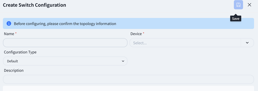
Default configuration type selection, the rest is the same as [Small/Mid-Scale Network Deployment], please refer to the previous section to complete the configuration.
Server Network Switch Group Wired Service Configuration
Section titled “Server Network Switch Group Wired Service Configuration”- Server Area Leaf
The Leaf switch of MC-LAG network needs to be configured with link aggregation port and business VLAN.
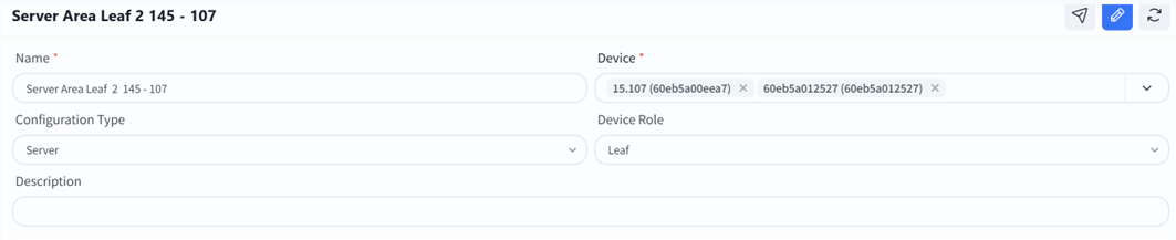
Select** [Configuration Type]**as server area.
Select** [Device] **as the leaf MC-LAG pair that needs to be configured.
Select **[Device Role] **as leaf.
Follow the prompts on the page to fill in the required business configuration.
Link Aggregation
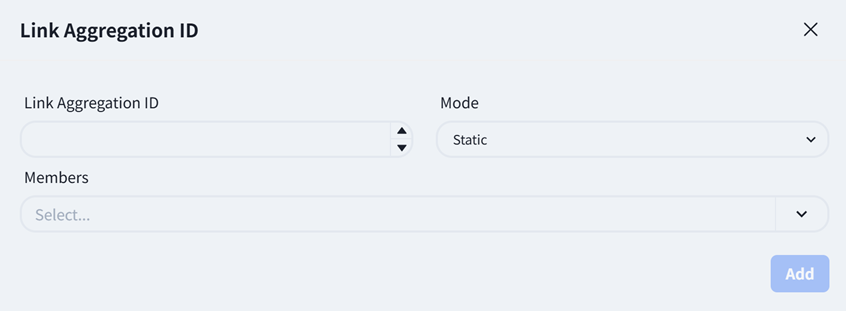
- **LAG: **Link Aggregation ID, users can create IDs within the range of 1501-2000 as needed.
- Mode: Static/LACP, choose whether the link aggregation mode is static or LACP dynamic negotiation.
- Member: Select the member interface connected to this business server.
Services VLAN
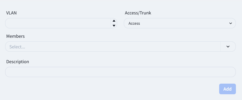
- **VLAN: **Users can fill in VLAN IDs ranging from 2 to 4050 as needed.
- **Access/Trunk: **The Access interface is used to connect terminal devices and belongs to a VLAN; The Trunk interface is used to connect network devices and allows traffic from multiple VLANs to pass through.
- **Member: **Member interfaces can only select LAG ports that have been configured in link aggregation.
- Server Area Spine
The business gateway of MC-LAG network is deployed on Spine devices, and when selecting devices, devices of Spine type also need to be added.
Create a business gateway for the business VLAN corresponding to the Leaf switch in the server area.
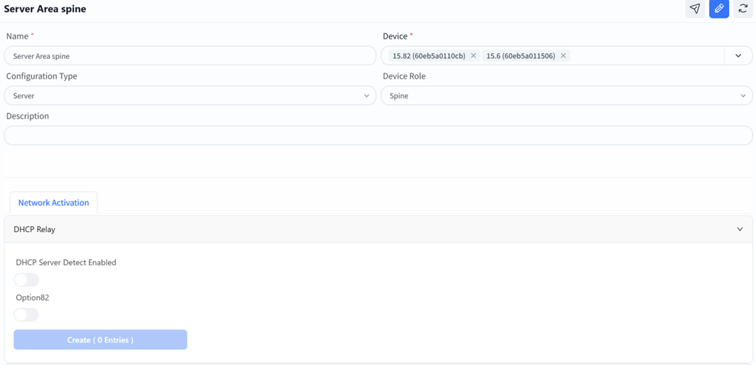
If the Spine downstream device needs to obtain an IP address from the Spine upstream DHCP server, a DHCP relay needs to be configured.
Services VLAN
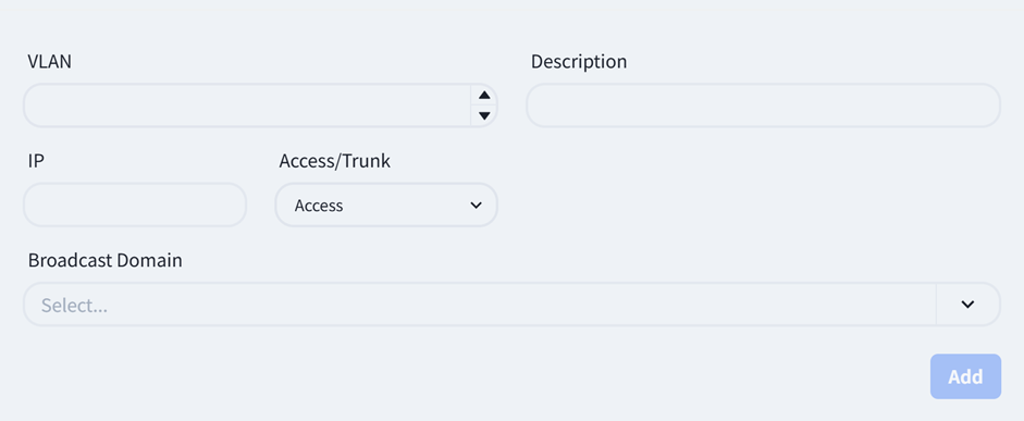
- **VLAN: **The business VLAN corresponding to the Leaf switch in the server area.
- IP: Fill in the gateway IP address of the business VLAN.
- **Access/Trunk: **The Access interface is used to connect terminal devices and belongs to a VLAN; The Trunk interface is used to connect network devices and allows traffic from multiple VLANs to pass through.
- **Broadcast domain: **Select the MAC address of the leaf switch corresponding to the VLAN.
Traditional L2 Network
Section titled “Traditional L2 Network”Unlike full L3 networks, the service network in traditional L2 networks is deployed on Spine devices. Therefore, when selecting devices, Spine-type devices must also be added.

If the DHCP Server is external, DHCP relay needs to be enabled on the Spine device so that the broadcast DHCP requests from the AP and the terminal can be converted into unicycle messages through DHCP relay and sent to the DHCP server.
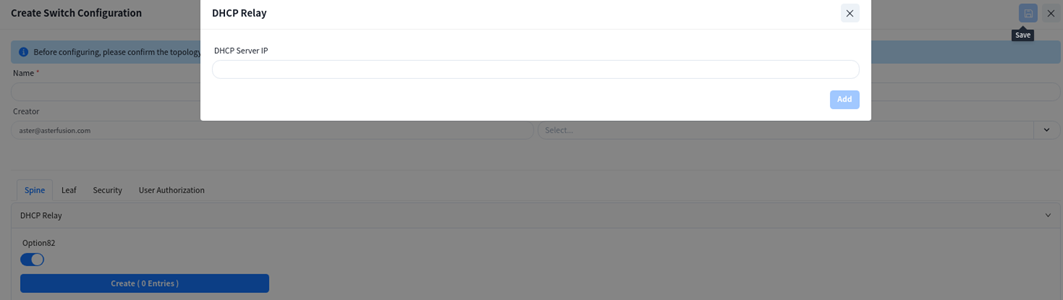
Create service VLAN:
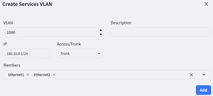
The Leaf switch is purely configured for Layer 2. On this interface, only the VLAN ID and member interfaces need to be specified, and all other configurations are generated by the controller.
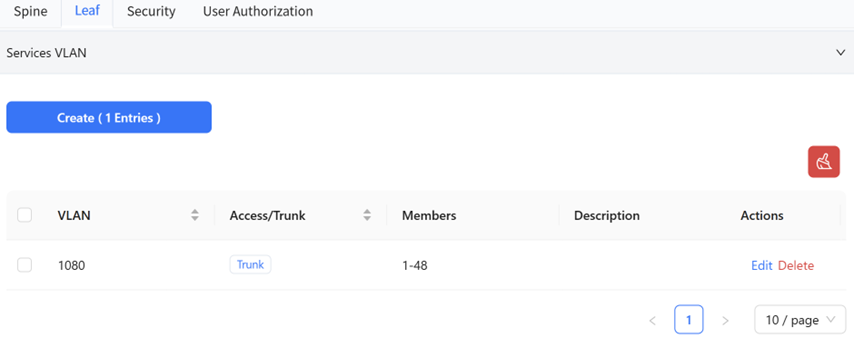
Open Cloud Connect
Section titled “Open Cloud Connect”The Open Cloud Connect scenario opens up the classic Layer 2 and Layer 3 functions of a single machine, and the gateway can be deployed on the aggregation or access device.
Gateway Deployed on Aggregation Devices
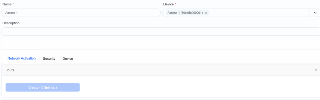
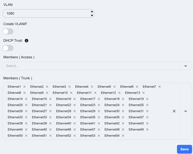
Section titled “Gateway Deployed on Aggregation Devices”When the gateway is deployed on aggregation devices, the Leaf switches are configured as pure Layer 2 devices. On this view, service VLAN IDs and member interfaces need to be specified, while the remaining configurations are generated by the controller.
Select the downstream and upstream port of the switch for the member interface of the services VLAN.
Gateway Deployed on Access Devices
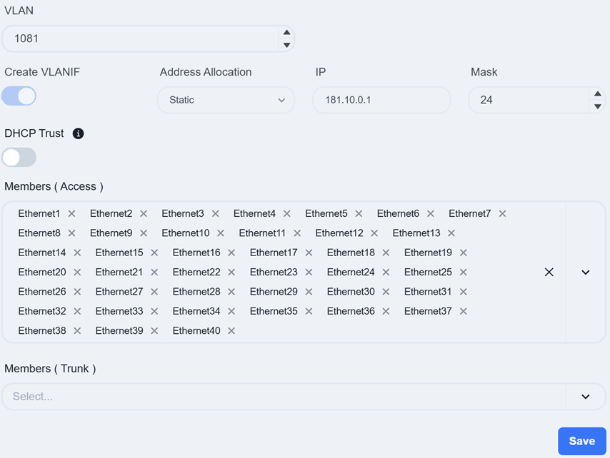
Section titled “Gateway Deployed on Access Devices”If the gateway is deployed on access devices, you need to enable 【Create VLANIF】 when creating the service VLAN and fill in the 【IP】 as the gateway address for this service.
Paragraph{indent=“1”} The DHCP Server, while allocating IP addresses to DHCP clients, can also assign IP addresses of servers that provide network services to DHCP clients. For instance, some clients similar to IP telephony, after automatically obtaining an IP address, still need to connect to a designated server to install software in order to function properly. Execute this command to configure the server address that the client will use next after automatically obtaining the IP address. After the client automatically acquires the IP address, it will request configuration information from the specified server.
- Vendor Specific (Option 43): Hexadecimal number used to transmit vendor specific information to client devices of a particular vendor.
If a third-party AP does not support or cannot recognize Option 138, the IP address of the controller can be specified for it by configuring Option 43 of the DHCP server.
- Server Identifier (Option 54): Notify the client of the address of the DHCP server.
Paragraph{indent=“1”} When there are multiple DHCP servers in the network, the client may receive multiple offers. The client clearly informs all servers of which one it has chosen by copying Option 54 from one of the offers into the Request it sent. The selected server will conduct the final confirmation, while the other servers will reclaim the IP addresses they have provided. When troubleshooting DHCP issues, packet capture and checking the Option 54 field is the most direct way to confirm which server the client is actually communicating with and whether the server address is correct.
- TFTP Server (Option 66): Configure the TFTP server address used by DHCP clients.
After the device starts up, it may need to obtain the configuration file from the TFTP server. This configuration enables the DHCP client to obtain the IP address of the TFTP server while acquiring the IP address, so that the client can access the server after startup and obtain the necessary information.
- Bootfile Name (Option 67): Configure the startup configuration file name for DHCP clients.
Paragraph{indent=“1”} In addition to assigning IP addresses to clients, DHCP servers can also provide network configuration parameters required by clients, such as startup configuration files, etc. After configuring this command, the OFFER and ACK messages sent by the DHCP server to the client will carry this file name. Then the DHCP client retrieves the startup configuration file from the specified file server based on the file name.
- **Controller IP:**DHCP options specifically designed for wireless AP discovery controllers, fill in the controller IP address.
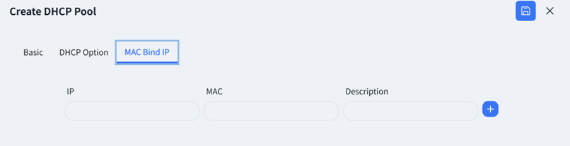
The controller supports configuring MAC binding IP function, which users can fill in as needed.
After completing the configuration, click save.