


Getting Started with Linux KVM
此内容尚不支持你的语言。
This document serves as a technical guide for deploying and validating a high-performance virtual network gateway using AsterNOS-VPP in a virtualized Linux environment. It outlines the environment requirements, configuration steps, and key technologies used throughout the process.
Target Audience
Section titled “Target Audience”This guide is designed for:
- Network engineers
- System administrators
- Developers
…who need to build a high-performance network testing or routing platform on top of QEMU/KVM with PCI Passthrough acceleration.
Prerequisites
Section titled “Prerequisites”To follow this guide effectively, readers should have basic proficiency in the following areas:
Linux Fundamentals
Section titled “Linux Fundamentals”Comfort with Linux command-line operations, including editing files and performing routine system administration tasks.
Networking Fundamentals
Section titled “Networking Fundamentals”Understanding of essential Layer-2/Layer-3 concepts such as IP addressing, subnet masks, default gateways, routing, and VLAN segmentation.
Virtualization Concepts
Section titled “Virtualization Concepts”Basic knowledge of Virtual Machines and host-guest architectures, ideally with some familiarity using QEMU/KVM.
Objective
Section titled “Objective”This document provides a step-by-step guide for deploying an AsterNOS-VPP virtual machine on an Ubuntu host using QEMU/KVM along with PCI Passthrough. The end goal is to build and verify a high-performance virtual router that supports:
- Inter-VLAN routing
- NAT for internet access
…within a virtualized test environment.
Applicable Models and Versions
Section titled “Applicable Models and Versions”Hardware
Section titled “Hardware”- Host Machine: ThinkCentre M8600t-N000 (example reference model).
- Network Adapter: Intel I350 Quad-Port Gigabit Ethernet.
- CPU Requirements: Processor must support the SSE4 instruction set. You can verify this using lscpu and checking that sse4 appears in the CPU flags.
Supported Network Adapters
Section titled “Supported Network Adapters”| Manufacturer | Series / Type | Vendor ID | Device ID / Class |
|---|---|---|---|
| Intel | All Network Devices | 0x8086 | Class 0x0200 |
| Intel | QAT Devices (VFs) | 0x8086 | Class 0x0b40 with Device IDs:0x0443, 0x18a1, 0x19e3, 0x37c9, 0x6f55, 0x18ef, 0x4941, 0x4943, 0x4945 |
| Cisco | VIC | 0x1137 | 0x0043, 0x0071 |
| Chelsio | T4/T5 | 0x1425 | 0x4000 - 0x5fff |
| Amazon | Elastic Network Adapter (ENA) | 0x1d0f | 0xec20, 0xec21 |
| Marvell (Cavium) | Legacy Cavium Adapters | 0x177d | 0x9712 |
| Marvell (QLogic) | FastlinQ QL41000 Series | 0x1077 | 0x1003, 0x1004 |
| Broadcom | NetXtreme S & E Series Only | 0x14e4 | 0x1604, 0x1605, 0x1614, 0x1606, 0x1609 All IDs > 0x16c0 EXCEPT: 0x16c6, 0x16c7, 0x16dd, 0x16f7, 0x16fd, 0x16fe, 0x170d, 0x170c, 0x170e, 0x1712, 0x1713 |
| vNIC | 0x1ae0 | 0x0042 |
Software
Section titled “Software”- Host Operating System: Ubuntu Linux 24.04
- Virtualization Stack: QEMU/KVM 8.2.2, libvirt 10.0.0
- Guest System: AsterNOS-VPP
License Activation(Optional)
Section titled “License Activation(Optional)”The system defaults to the Free Edition. To unlock **Commercial Edition **features, follow these steps:
- **Get Serial Number: **Run
show versionin the SONiC CLI and note the Serial Number. - **Obtain License: **Send the SN to us to receive your license file.
- Install File: Upload the license file to the directory
/etc/sonic/lic/. - Apply License: Run one of the following commands to activate:
- Bash:
sudo licmgrdctl update - CLI:
license update
- Bash:
Feature Overview
Section titled “Feature Overview”PCI Passthrough
Section titled “PCI Passthrough”A virtualization feature that assigns a physical hardware device directly to a VM, giving the VM exclusive access and enabling near-native performance.
Inter-VLAN Routing
Section titled “Inter-VLAN Routing”A routing function that enables communication between different network segments by creating virtual Layer-3 interfaces for each VLAN.
Network Address Translation (NAT)
Section titled “Network Address Translation (NAT)”Allows devices in private subnets to access the public internet by reusing the router’s public IP address.
Typical Deployment Example: Dual-Subnet Routing + NAT
Section titled “Typical Deployment Example: Dual-Subnet Routing + NAT”Requirements
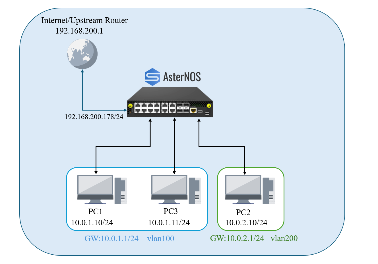
Section titled “Requirements”Deploy an AsterNOS-VPP virtual router with one dedicated WAN port and multiple dedicated physical LAN ports via PCI Passthrough.
- Group the LAN ports into two VLANs, each connecting to a separate PC or subnet.
- Ensure both PCs/subnets have internet access via the VM’s NAT.
- Ensure hosts in both VLANs can communicate with each other through inter-VLAN routing.
Topology
Section titled “Topology”- Physical Connections:
- Host ens3f0 (PCI Address 02:00.0) -> Upstream Router (WAN)
- Host ens3f1 (PCI Address 02:00.1) -> PC1 (LAN1)
- Host ens3f2 (PCI Address 02:00.2) -> PC2 (LAN2)
- Host ens3f3 (PCI Address 02:00.3) -> PC3 (LAN3)
Environment
Section titled “Environment”| Device Type | Model/System | Role/Description |
|---|---|---|
| Host Machine | ThinkCentre-M8600t-N000 | Ubuntu, QEMU/KVM,libvirt Host |
| VM | AsterNOS-VPP | 8GB RAM, 4-Core CPU,64GB DISK |
| PC1 | Windows PC | LAN1 Client, connected to ens3f1 |
| PC2 | Windows PC | LAN2 Client, connected to ens3f2 |
| PC3 | Windows PC | LAN3 Client, connected to ens3f3 |
| Network Plan | Interface (AsterNOS ) | IPAddress / Range | Description |
|---|---|---|---|
| WAN | Ethernet1 | 192.168.200.178/24 | Connects to upstream router 192.168.200.1 |
| LAN1 | Vlan100 | 10.0.1.0/24 | Subnet for PC1 and PC3, Gateway 10.0.1.1 |
| LAN2 | Vlan200 | 10.0.2.0/24 | Subnet for PC2, Gateway 10.0.2.1 |
Software Acquisition
Section titled “Software Acquisition”- **Software Download **Link
Click To Download SONiC-vpp.imgnote NOTE: The .img file provided in this guide is a pre-installed Virtual Disk Image (VDI). It contains virtual drivers intended only for use in virtualized environments.
Configuration Steps on Ubuntu Host
Section titled “Configuration Steps on Ubuntu Host”BIOS/UEFI Settings:
Section titled “BIOS/UEFI Settings:”Objective: To enable the IOMMU function at the firmware level (BIOS/UEFI), making the hardware feature available to the operating system.
Action: Reboot the host and enter the BIOS/UEFI setup. Ensure that both Intel(R) VT-d and Intel(R) Virtualization Technology are enabled.
GRUB Parameter Configuration:
Section titled “GRUB Parameter Configuration:”Objective: To instruct the Linux kernel to activate and use the IOMMU feature that was enabled in the firmware.Terminal window
**Action: **Edit the GRUB configuration files /etc/default/grub, find the line starting with GRUB_CMDLINE_LINUX_DEFAULT and add “intel_iommu=on iommu=pt” inside the quotes.
#sudo nano /etc/default/grubGRUB_CMDLINE_LINUX_DEFAULT="quiet splash intel_iommu=on iommu=pt"#Update the GRUB configuration by sudo update-grubConfigure VFIO Driver:
Section titled “Configure VFIO Driver:”Objective: To use the dedicated vfio-pci driver to take control of the physical NICs intended for passthrough. This prevents the host OS from loading its default drivers, making the NICs available to the VM.
Action:
- Find the NIC’s Device ID ::: BlockQuote # This command lists all network devices and their IDs lspci -nn | grep -i ethernet
hint{type=“warning”} Important Notice: Network Port Order The order of interfaces such as Ethernet1, Ethernet2, etc., as recognized internally by AsterNOS-VPP, is determined by the order of the -device parameters in the QEMU startup command (i.e., the order of PCI addresses). This order may not match the physical arrangement of network ports on the back panel of your server chassis (e.g., top to bottom, left to right).
BlockQuote sudo virsh console AsterNOS
Log In and Enter Configuration Mode: At the login prompt, use the default credentials to access the system:
- Username: admin
- Password: asteros
Step-by-Step Configuration and Verification:
- Launch the command-line interface & Enter configuration mode
admin@sonic:\~$ sonic-cliconfigure terminal
2. **Configure WAN Interface**
BlockQuote
sonic(config)# interface ethernet 1
sonic(config-if-1)# description WAN_Port
sonic(config-if-1)# ip address 192.168.200.178/24
# Assign this interface to NAT zone 1.
# By convention, the outside (WAN) interface is a non-zero zone,
# and inside interfaces are zone 0.
sonic(config-if-1)# nat-zone 1
sonic(config-if-1)# exit
- Configure VLANs and Gateway Interfaces
sonic(config)# vlan 100sonic(config-vlan-100)# exit
sonic(config)# vlan 200sonic(config-vlan-200)# exit
sonic(config)# interface vlan 100sonic(config-vlan-if-100)# description LAN1_Gateway_for_PC1_and_PC3sonic(config-vlan-if-100)# ip address 10.0.1.1/24sonic(config-vlan-if-100)# exit
sonic(config)# interface vlan 200sonic(config-vlan-200)# description LAN2_Gateway_for_PC2sonic(config-vlan-200)# ip address 10.0.2.1/24sonic(config-vlan-200)# exit
4. **Assign Physical LAN Ports to VLANs**
BlockQuote # Connects to PC1 sonic(config)# interface ethernet 2 sonic(config-if-2)# description Port_for_PC1 sonic(config-if-2)# switchport access vlan 100 sonic(config-if-2)# exit
# Connects to PC2 sonic(config)# interface ethernet 3 sonic(config-if-3)# description Port_for_PC2 sonic(config-if-3)# switchport access vlan 200 sonic(config-if-3)# exit
# Connects to PC3 sonic(config)# interface ethernet 4 sonic(config-if-4)# description Port_for_PC3 sonic(config-if-4)# switchport access vlan 100 sonic(config-if-4)# exit
- Configure Routing and NAT
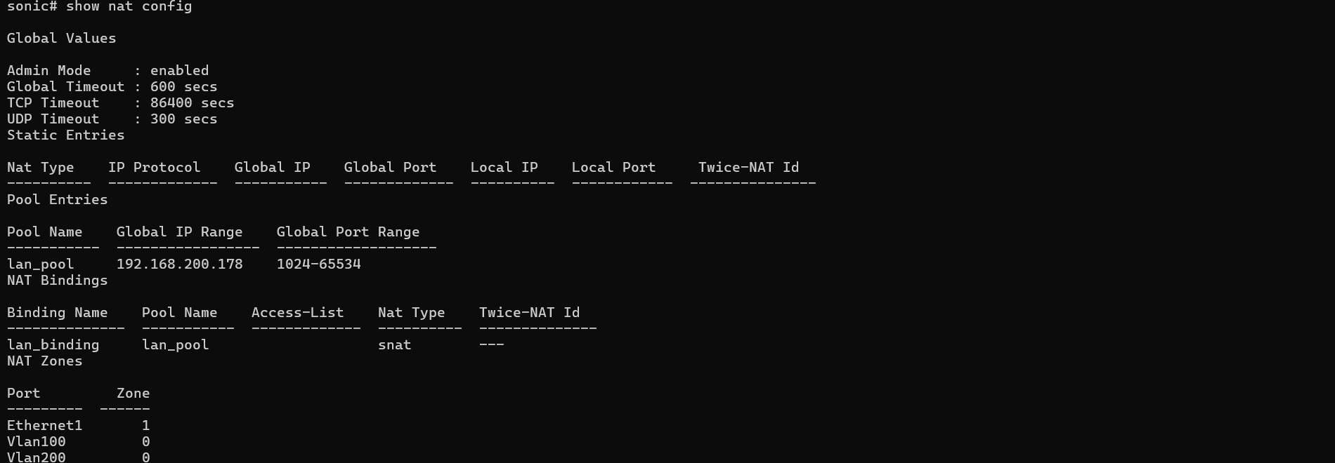
\# Configure the default route to point to the upstream routersonic(config)# ip route 0.0.0.0/0 192.168.200.1
\# Enable NAT globallysonic(config)# nat enable
\# Create a NAT pool named 'lan_pool'\# using the router's public IPsonic(config)# nat pool lan_pool 192.168.200.178
\# Bind the pool to a policy named 'lan_binding'\# to apply NAT to all traffic crossing zonessonic(config)# nat binding lan_binding lan_pool
6. **Save Configuration**
BlockQuote sonic(config)# write
- **Verify Configuration: **Please ensure that the Admin/Oper status of the interface shows up/up.
sonic# show ip interfaces sonic# show ip route sonic# show vlan summary sonic# show nat config



Configuration Steps: Client PCs
Section titled “Configuration Steps: Client PCs”- PC1: Set IP to 10.0.1.10, subnet mask to 24, gateway to 10.0.1.1, and DNS to 8.8.8.8.
- PC2: Set IP to 10.0.2.10, subnet mask to 24, gateway to 10.0.2.1, and DNS to 8.8.8.8.
- PC3: Set IP to 10.0.1.11, subnet mask to 24, gateway to 10.0.1.1, and DNS to 8.8.8.8.
Function and Performance Verification
Section titled “Function and Performance Verification”This chapter will comprehensively verify that the virtual router’s core functions and performance metrics meet expectations through a series of tests.
Overall Test Plan
Section titled “Overall Test Plan”We will proceed with the following sequence of tests:
- Layer 2 Switching Performance (Intra-VLAN): Use iperf3 to test the transfer rate between PC1 and PC3 to verify switching performance within the same VLAN.
- Layer 3 Routing Performance (Inter-VLAN): Use iperf3 to test the transfer rate between PC1 and PC2 to verify routing performance between different VLANs, monitored with router-side commands.
- External Connectivity (NAT Verification): Use ping to test if internal PCs can access the public internet, verifying basic NAT connectivity.
Layer 2 Switching Performance Test (PC1 <-> PC3)
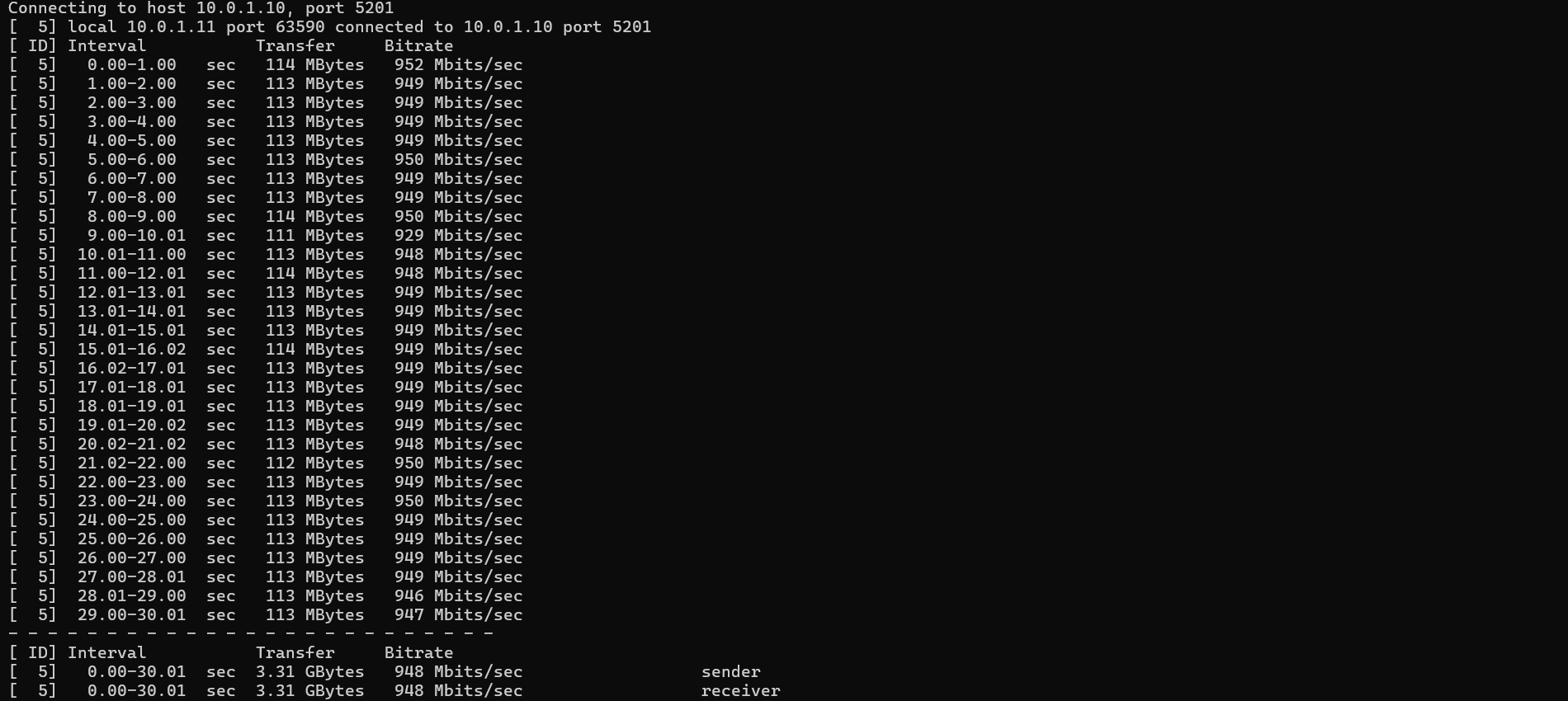
Section titled “Layer 2 Switching Performance Test (PC1 <-> PC3)”Objective: To verify the Layer 2 (L2) data forwarding capability of the virtual router within the same VLAN. Since PC1 and PC3 are both in VLAN 100, communication between them is handled by L2 switching.
Procedure:
- On PC1 (10.0.1.10), open a command prompt and ensure the iperf3 server is running: iperf3 -s.
- On PC3 (10.0.1.11), open a command prompt and execute the client test: iperf3 -c 10.0.1.10 -t 30.
- Results Analysis: The test rate should stabilize around 950 Mbits/sec, achieving Gigabit line-rate.
Layer 3 Routing Performance Test (PC1 <-> PC2)
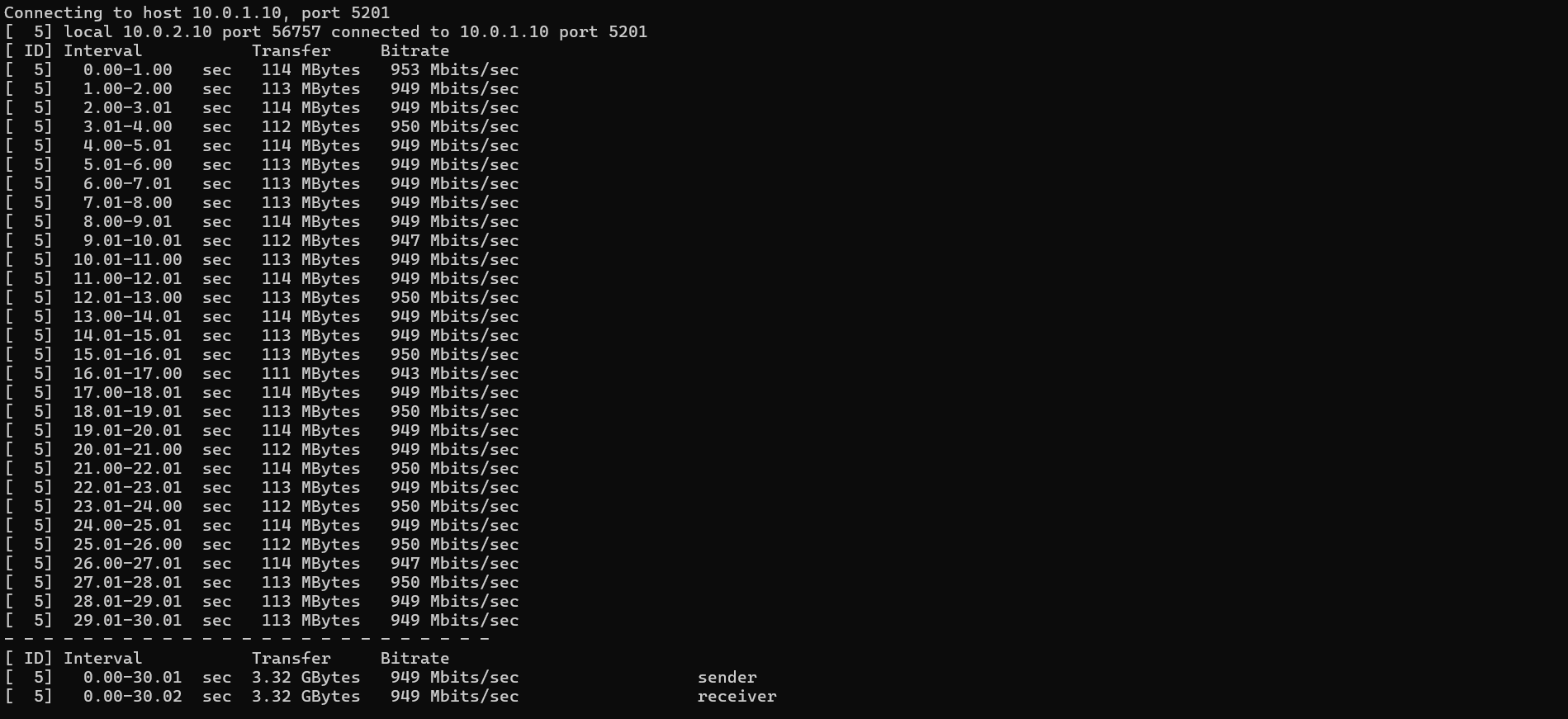
Section titled “Layer 3 Routing Performance Test (PC1 <-> PC2)”Objective: To verify the Layer 3 (L3) routing performance of the virtual router between different VLANs. Communication between PC1 (VLAN 100) and PC2 (VLAN 200) requires L3 routing.
Procedure:
- On PC1 (10.0.1.10), open a command prompt and ensure the iperf3 server is running: iperf3 -s.
- On PC2 (10.0.2.10), open a command prompt and execute the client test: iperf3 -c 10.0.1.10 -t 30.
Results Analysis: The test rate should also achieve line-rate performance of around 950 Mbits/sec.
Router-Side Verification: During the iperf3 test, you can monitor the interface statistics in real-time on the AsterNOS device by running show counters interface. As seen above, the receive (RX) rate for Ethernet3 (connected to PC2) is approximately 1000 Mbits/s, which perfectly matches the iperf3 results.

Internet Access Function Test
Section titled “Internet Access Function Test”Objective: To verify that the NAT function is effective for all internal VLANs.
Ping Connectivity Test:
- On PC1 (VLAN 100), ping 8.8.8.8. You should receive successful replies.

- On PC2 (VLAN 200), ping 8.8.8.8. You should also receive successful replies.

Conclusion
Section titled “Conclusion”This guide demonstrates that AsterNOS-VPP successfully combines the robust SONiC ecosystem with the high-performance VPP data plane.
By leveraging virtual machines and PCI passthrough on standard x86 servers, users can easily build an enterprise-grade virtual gateway capable of line-rate Layer 2/3 forwarding and NAT. For network environments seeking high performance, flexibility, and cost efficiency, AsterNOS-VPP is an ideal solution.