


HQoS-VPP Case
此内容尚不支持你的语言。
This guide provides a step-by-step tutorial for configuring Hierarchical Quality of Service (HQoS) on the Asterfusion ET2500 Open Intelligent Gateway running AsterNOS.
Unlike traditional “Flat QoS” which only manages traffic based on interface or packet priority, HQoS introduces the concept of Organization into your network. It allows you to model your traffic policies based on real-world structures—Tenants, Departments, and Users—ensuring critical business isolation in congested environments.
What This Guide Will Accomplish
Section titled “What This Guide Will Accomplish”By following this guide, you will upgrade a standard Layer 3 gateway into an intelligent, multi-tenant traffic manager. You will learn how to map the logical 4-Level Scheduler Hierarchy (Port - Group - User - Queue) to enforce strict Service Level Agreements (SLAs).
The scenarios covered are:
- Phase 1: Multi-Tenant Resource Isolation (Group Shaping) We will configure two distinct departments: “R&D” and “Guest”. We will demonstrate that the “Guest Zone” is strictly capped at a specific bandwidth,preventing it from affecting the “R&D Department” even when the Guests try to flood the network.
- Phase 2: Micro-Level Service Assurance (Queue Scheduling) Within the R&D bandwidth pipe, we will implement a “Voice First” policy. We will verify that Latency-Sensitive traffic strictly pre-empts Bulk Data during congestion.
- Phase 3: Traffic Classification & Mapping Learning how to use Access Control Lists (ACLs) to classify traffic from different physical subnets and map them into their respective HQoS logic branches.
Supported Platforms & Modes
Section titled “Supported Platforms & Modes”AsterNOS HQoS is designed with a unified architecture that adapts to your underlying hardware:
- Hardware Mode: On supported platforms (e.g., ET2500), HQoS policies can be offloaded to the NPU for zero-CPU-overhead execution.
- Software Mode: On standard VMs or non-NPU interfaces, HQoS runs in Software Mode (VPP-based), providing identical functionality with CPU-dependent performance.
BlockQuote #1. Global NAT Enable sonic(config)# nat enable #2. Configure NAT Pool (Using WAN IP) sonic(config)# nat pool pool1 192.168.200.166 #3. Configure NAT Binding sonic(config)# nat binding bind1 pool1 #4. Configure WAN Interface (Ethernet 1) sonic(config)# interface ethernet 1 sonic(config-if-1)# ip address 192.168.200.166/24 sonic(config-if-1)# nat-zone 1 sonic(config-if-1)# exit #5. Configure LAN Interface 1 (Ethernet 2 - R&D) sonic(config)# interface ethernet 2 sonic(config-if-2)# ip address 10.10.10.1/24 sonic(config-if-2)# exit #6. Configure LAN Interface 2 (Ethernet 3 - Guest) sonic(config)# interface ethernet 3 sonic(config-if-3)# ip address 10.20.20.1/24 sonic(config-if-3)# exit #7. Configure Default Route sonic(config)# ip route 0.0.0.0/0 192.168.200.1
Building the HQoS Hierarchy
Section titled “Building the HQoS Hierarchy”We construct the HQoS policy from the bottom up: Maps -> User Profile -> Group Profile -> Port Profile.
Step 1: QoS Mapping (DSCP to TC)
Section titled “Step 1: QoS Mapping (DSCP to TC)”Define how packets are mapped to internal Traffic Classes.
#Map DSCP 0 (Data) to TC 0sonic(config)# qos map dscp_to_tc voice-prio 0 0 #Map DSCP 46 (Voice) to TC 7sonic(config)# qos map dscp_to_tc voice-prio 46 7
## Step 2: User Profiles (Queue Scheduling)
We define two user templates: one for standard employees (R\&D) who need voice priority, and one for guests who only get best-effort service.
BlockQuote #Template for R&D Employees sonic(config)# hqos-user-profile emp-standard #Bind the map for egress queue alignment sonic(config-user-emp-standard)# qos-map bind dscp_to_tc voice-prio #Queue 0: DWRR (Data) sonic(config-user-emp-standard)# tc-queue 0 mode dwrr 1 #Queue 7: Strict Priority (Voice) sonic(config-user-emp-standard)# tc-queue 7 mode strict sonic(config-user-emp-standard)# exit #Template for Guests sonic(config)# hqos-user-profile emp-guest sonic(config-user-emp-guest)# tc-queue 0 mode dwrr 1 sonic(config-user-emp-guest)# exit
Step 3: User Group Profiles (Department Isolation)
Section titled “Step 3: User Group Profiles (Department Isolation)”Here we define the bandwidth limits for each department.
#Group 1: R&D Department #R&D Group Limit: ~100 Mbps (12,500,000 Bytes/s)#R&D User Limit: ~50 Mbps (6,250,000 Bytes/s)sonic(config)# hqos-user-group-profile rd-deptsonic(config-group-rd-dept)# user-profile emp-standard shaping pir 6250000 pbs 1000000sonic(config-group-rd-dept)# exit #Group 2: Guest Zone#Guest Group Limit: ~25 Mbps (3,125,000 Bytes/s)sonic(config)# hqos-user-group-profile guest-zonesonic(config-group-guest-zone)# user-profile emp-guest shaping pir 3125000 pbs 1000000sonic(config-group-guest-zone)# exitnote Note: ***pir ***is in Bytes/sec. pbs is in Bytes. We set pbs to ~1MB to ensure smooth TCP performance.
Step 4: Port Profile (Global Level)
Section titled “Step 4: Port Profile (Global Level)”Define the physical port limit and attach the department groups. ::: BlockQuote sonic(config)# hqos-profile wan-policy #Global Port Rate sonic(config-hqos-wan-policy)# global rate 125000000 #Attach R&D Group (Limit: 100 Mbps) sonic(config-hqos-wan-policy)# user-group-profile rd-dept shaping pir 12500000 pbs 1000000 #Attach Guest Group (Limit: 25 Mbps) sonic(config-hqos-wan-policy)# user-group-profile guest-zone shaping pir 3125000 pbs 1000000 sonic(config-hqos-wan-policy)# exit #Enable HQoS Globally sonic(config)# hqos enable
Classification & Application
Section titled “Classification & Application”Now we map the subnets to the correct profiles and apply them to interfaces.
Step 1: Classification (ACL)
Section titled “Step 1: Classification (ACL)”Identify traffic from the LAN subnets and mark them with the correct User Profile.
sonic(config)# access-list L3 download-class ingress #Rule 1: Map 10.10.10.x (Port 2) to R&D Usersonic(config-L3-acl-download-class)# rule 1 src-ip 10.10.10.0/24 packet-action permit set-hqos-user emp-standard #Rule 2: Map 10.20.20.x (Port 3) to Guest Usersonic(config-L3-acl-download-class)# rule 2 src-ip 10.20.20.0/24 packet-action permit set-hqos-user emp-guestsonic(config-L3-acl-download-class)# exit
## Step 2: Interface Binding
Apply the configuration to the physical ports.
BlockQuote #WAN Interface sonic(config)# interface ethernet 1 sonic(config-if-1)# hqos-profile wan-policy sonic(config-if-1)# exit #LAN Interface 1 (Port 2 - R&D) sonic(config)# interface ethernet 2 sonic(config-if-2)# qos-map bind dscp_to_tc voice-prio #Apply ACL sonic(config-if-2)# acl download-class priority 10 sonic(config-if-2)# exit #LAN Interface 2 (Port 3 - Guest) sonic(config)# interface ethernet 3 #Apply ACL sonic(config-if-3)# acl download-class priority 10 sonic(config-if-3)# exit
Verification Scenario 1: Inter-Department Isolation
Section titled “Verification Scenario 1: Inter-Department Isolation”This test validates the “Firewall” between departments. We demonstrate that even when the Guest Zone attempts to saturate the network with excessive traffic (DoS simulation), the R&D Department remains completely unaffected.
Test Setup
Section titled “Test Setup”- Bottleneck: None at the Port level (1 Gbps), but strict shaping at the Group level.
- Victim (Guest Zone): Configured with a hard cap of 25 Mbps.
- Observer (R&D Dept): Configured with a guaranteed 100 Mbps.
- Attack Scenario: The Guest PC attempts to blast 100 Mbps of traffic while R&D is transferring critical data at 40 Mbps.
Validation Command
Section titled “Validation Command”We execute these commands simultaneously on two different terminals (representing Port 3 and Port 2).
## Terminal A (Guest - Port 3): Attempt to use 100Miperf3 -c <Server_IP> -p 5202 -u -b 100M -t 20
## Terminal B (R&D - Port 2): Normal usage 40Miperf3 -c <Server_IP> -p 5201 -u -b 40M -t 20
Observed Result
Section titled “Observed Result”The screenshots below illustrate perfect isolation:
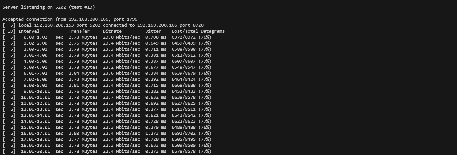
- The Guest (Suppressed):
As shown in the first screenshot, despite requesting 100 Mbps, the Guest traffic is ruthlessly throttled by the HQoS Group Shaper.
- Throughput: Flatlines at ~23.4 Mbps (Effective Payload for a 25M Shaper).
- Packet Loss: High loss (~77%) confirms that excess traffic is dropped at the ingress, preventing it from consuming shared resources.
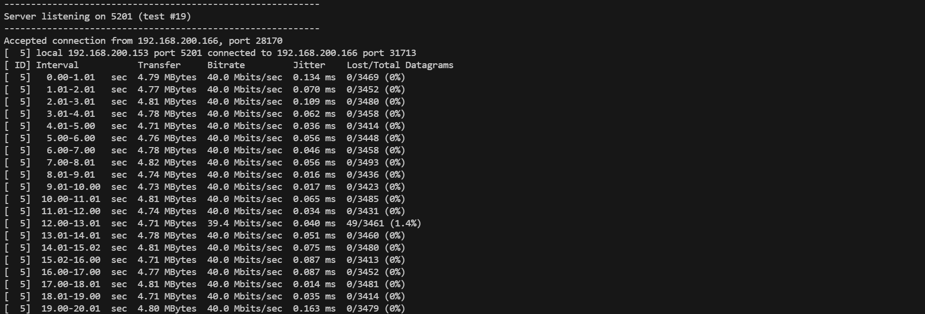
- The R&D Department (Unaffected):
Simultaneously, the R&D traffic flows without interruption.
- Throughput: Maintains a rock-solid 40.0 Mbps.
- Packet Loss: 0%. The congestion in the Guest Zone does not bleed over into the R&D Zone.
Verification Scenario 2: Service Assurance (R&D Internal)
Section titled “Verification Scenario 2: Service Assurance (R&D Internal)”To verify the HQoS logic within the R&D department, we simulate a congestion scenario where the total traffic demand exceeds the configured User Shaper bandwidth.
Test Setup
Section titled “Test Setup”- Bottleneck: R&D User Profile limited to 50 Mbps (PIR).
- Traffic A (VIP Voice): 30 Mbps stream (DSCP 46, Queue 7, Strict Priority).
- Traffic B (Bulk Data): 40 Mbps stream (DSCP 0, Queue 0, DWRR).
- Total Demand: 70 Mbps > 50 Mbps (Congestion Triggered!).
Validation Command****
Section titled “Validation Command****”** **We initiate the Bulk Data stream first to saturate the link, then inject the Voice stream to observe pre-emption.
## Terminal 1: Bulk Data (Target Port 5201)iperf3 -c <Server_IP> -p 5201 -u -b 40M --dscp 0 -t 30
## Terminal 2: Voice (Target Port 5202) - The "VIP"## Start this 10 seconds after Terminal 1iperf3 -c <Server_IP> -p 5202 -u -b 30M --dscp 46 -t 10
Observed Result
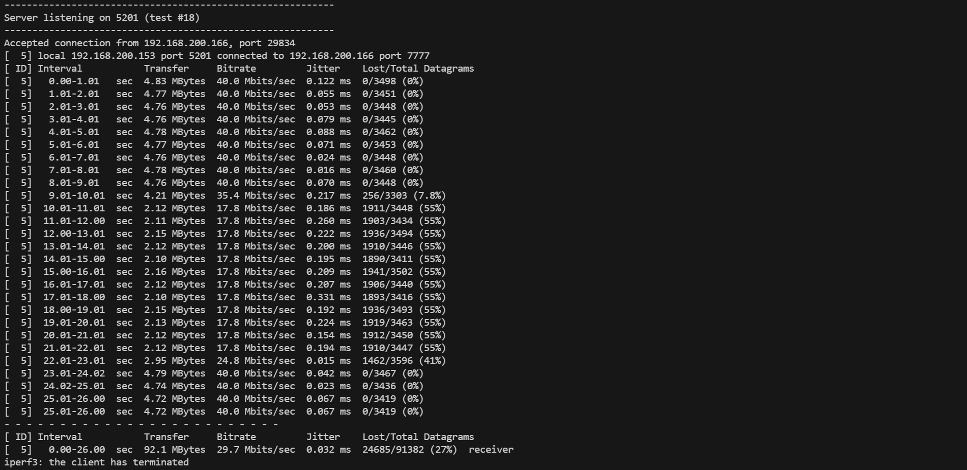
Section titled “Observed Result”As shown in the screenshot below, the HQoS scheduler exhibits textbook Strict Priority behavior:
- Phase 1 (0s - 9s): The Bulk Data stream (DSCP 0) runs alone, utilizing 40 Mbps with 0% packet loss.
- Phase 2 (Congestion): As soon as the Voice stream (DSCP 46) starts, it instantly claims its required 30 Mbps.
- The Squeeze: The Bulk Data stream is immediately throttled down.
- Math: 50 Mbps (Total) - 30 Mbps (VIP)= 20 Mbps (Remaining).
- Actual: The iperf3 output shows the Bulk stream stabilizing at ~17.8 Mbps.
Note: The difference between 20 Mbps (Physical) and 17.8 Mbps (Throughput) is due to Ethernet/IP/UDP header overheads.
- Phase 3 (Recovery): Once the Voice stream stops, the Bulk Data stream immediately recovers to full capacity.
Conclusion
Section titled “Conclusion”This guide has successfully demonstrated the implementation of a 4-level **Hierarchical Quality of Service (HQoS) **architecture on the Asterfusion ET2500 gateway. It verifies the comprehensive QoS capabilities of AsterNOS, enabling granular traffic management from basic port limits to complex flow-based and elastic bandwidth strategies. This validated configuration transforms the gateway into a powerful, service-aware edge device capable of enforcing complex Service Level Agreements (SLAs) in multi-tenant environments.